Multi-degree of freedom electromagnetic damper

A technology of electromagnetic dampers and degrees of freedom, applied in the directions of magnetic springs, springs/shock absorbers, springs, etc., can solve the problems of large fluctuation of damping force and asymmetric distribution of damping force, and achieve large damping force, small deformation and distribution. symmetrical effect

Active Publication Date: 2012-10-10
HARBIN INST OF TECH
View PDF4 Cites 29 Cited by
  • Summary
  • Abstract
  • Description
  • Claims
  • Application Information

AI Technical Summary

Problems solved by technology

[0004] The present invention provides a multi-degree-of-freedom electromagnetic damper in order to solve the problem that the damping force fluctuates greatly and the damping force distribution generated by the existing electromagnetic damper is asymmetrical.

Method used


Image

  • Multi-degree of freedom electromagnetic damper
  • Multi-degree of freedom electromagnetic damper
  • Multi-degree of freedom electromagnetic damper

Examples


specific Embodiment approach 1

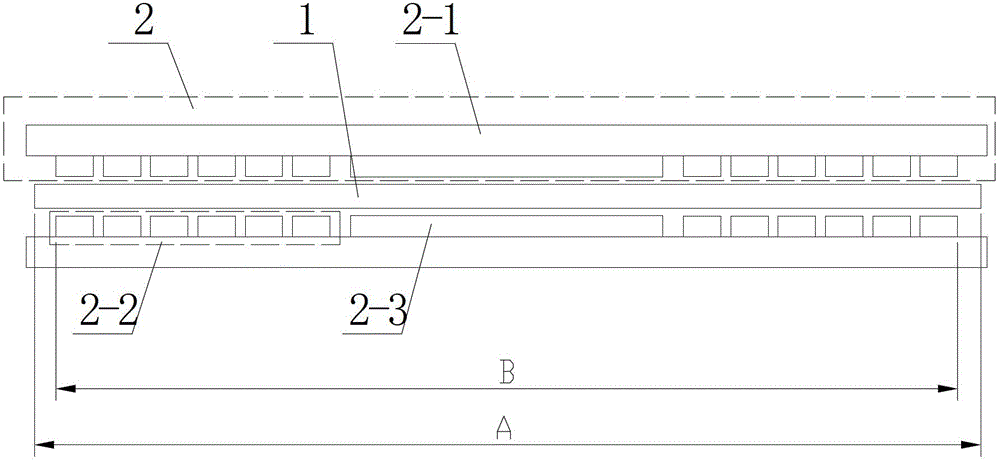
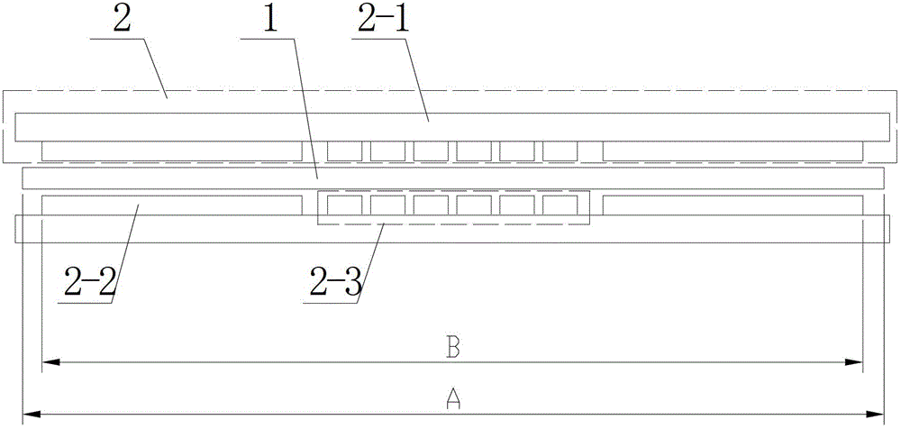
[0039] Specific implementation mode one: the following combination Figure 1 to Figure 4Describe this embodiment, the multi-degree-of-freedom electromagnetic damper in this embodiment includes a primary 1 and two secondary 2, the primary 1 is a low-resistivity non-magnetic metal plate, and the two secondary 2 are symmetrically distributed On both sides of primary 1, an air gap is formed between each secondary 2 and primary 1,

[0040] Each secondary 2 includes a secondary yoke plate 2-1, n+1 groups of X-direction excitation units 2-2 and n groups of Y-direction excitation units 2-3, where n is a positive integer,

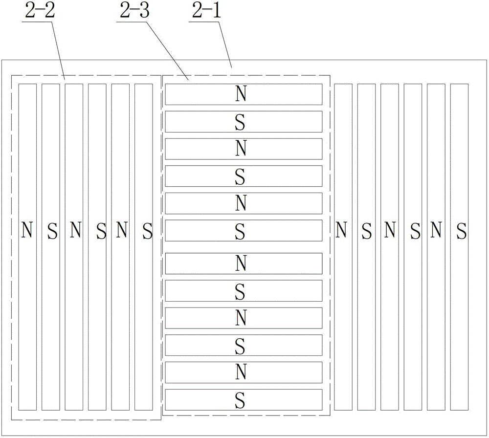
[0041] n+1 groups of X-direction excitation units 2-2 and n groups of Y-direction excitation units 2-3 are arranged on the secondary yoke plate 2-1 at equal intervals in turn, and each group of X-direction excitation units 2-2 consists of multiple pieces Composed of elongated permanent magnets, the multiple elongated permanent magnets are evenly arranged in the sam...

specific Embodiment approach 2

[0045] Specific implementation mode two: the following combination Figure 1 to Figure 4 This embodiment is described. This embodiment is a further description of Embodiment 1. The plurality of elongated permanent magnets of the X-direction excitation unit 2-2 are arranged along the length direction or width direction of the secondary yoke plate 2-1.

specific Embodiment approach 3

[0046] Specific implementation mode three: the following combination Figure 5 Describe this embodiment, this embodiment is a further description of Embodiment 1 or 2, the plurality of elongated permanent magnets of the X-direction excitation unit 2-2 are arranged along the length direction of the secondary yoke plate 2-1, the Each elongated permanent magnet is composed of three longitudinal segments of permanent magnets along its length direction, and the intervals between the three segments of permanent magnets are equal; The level yoke plates 2-1 are arranged in the width direction, and each elongated permanent magnet is composed of two transverse segments of permanent magnets along its length direction, and there is a distance between the two transverse segments of permanent magnets.

[0047] In this embodiment, Figure 5 As shown, there are 2 sets of X-direction excitation units 2-2 and 1 group of Y-direction excitation units 2-3. The elongated permanent magnet is divid...


PUM


Abstract

The invention discloses a multi-degree of freedom electromagnetic damper which belongs to the technical field of motors, solving the problems of the traditional electromagnetic damper of large damping force fluctuation and asymmetric distribution of generated damping force. The multi-degree of freedom electromagnetic damper mainly comprises a primary coil and secondary coils, wherein the primary coil mainly comprises a low-resistivity non-magnetic metal plate, the two-side secondary coils are distributed on the upper side and the lower side of the primary coil symmetrically, two air gaps are arranged between the primary coil and the two-side secondary coils, each-side secondary coil mainly comprises a yoke plate, (n+1) groups of X-direction excitation units and n groups of Y-direction excitation units, n is a positive integer, each X-direction excitation unit or Y-direction excitation unit comprises a plurality of strip-shaped permanent magnets which are sequentially and uniformly arranged on the flat yoke plates along the same direction, the magnetizing direction is vertical to a plane where the air gaps exist, magnetizing directions of every two adjacent permanent magnets are opposite, and magnetizing directions of permanent magnets on the two-side secondary coils corresponding to two sides of the primary coil are the same. The multi-degree of freedom electromagnetic damper is suitable for an electromagnetic damper.

Description

technical field [0001] The invention relates to a multi-degree-of-freedom electromagnetic damper, which belongs to the technical field of motors. Background technique [0002] In the lithography machine device, there are many moving parts, such as mask table movers, silicon wafer table movers, and balance masses. In order to reduce the vibration during the movement of the moving parts and to quickly attenuate Unnecessary motion, usually requires an electromagnetic damper. In other motion control fields, electromagnetic dampers can also be used in order to quickly dampen the motion between two moving bodies. [0003] Electromagnetic dampers are usually composed of permanent magnets or electromagnets that can generate a magnetic field and a conductor plate with good conductivity. When there is relative motion between the two, eddy currents will be induced in the conductor plate. The interaction between the eddy current and the magnetic field of the permanent magnet will gene...

Claims


Application Information

Patent Timeline
Patent Type & Authority Applications(China)
IPC IPC(8): F16F6/00
Inventor 寇宝泉张赫金银锡张鲁
Owner HARBIN INST OF TECH
Why Eureka
Try Eureka