Check patentability & draft patents in minutes with Patsnap Eureka AI!

Flue gas heating device and flue gas heating method

A flue gas heating and heater technology, which is applied in the field of electric power environmental protection, can solve the problems of general products and methods that do not have appropriate structures and methods, low overall economy, and large flow of circulating medium, so as to reduce temperature and save water consumption. , the effect of inhibiting corrosion

Inactive Publication Date: 2012-10-10
舒少辛 +2
View PDF5 Cites 0 Cited by
  • Summary
  • Abstract
  • Description
  • Claims
  • Application Information

AI Technical Summary

Problems solved by technology

Since the temperature of the flue gas needs to be heated above 65°C, the medium temperature of the low-temperature flue gas passing through the outlet of the desulfurization tower should be relatively high, generally above 85°C, while the temperature of the high-temperature flue gas is only around 140°C , so the heat absorbed by the medium per unit mass at the high-temperature end and the heat released at the low-temperature end are relatively small, which requires a large flow rate of the circulating medium, which leads to high power consumption of the circulating pump
At the same time, due to the small heat transfer temperature difference, a large number of heating surfaces need to be provided, so the overall economy is not high, which also limits the use of this technology
[0004] It can be seen that the above-mentioned existing flue gas heating device and method obviously still have inconvenience and defects in product structure, method and use, and need to be further improved urgently.
In order to solve the above-mentioned problems, the relevant manufacturers have tried their best to find a solution, but no suitable design has been developed for a long time, and there is no suitable structure and method for general products and methods to solve the above-mentioned problems. This is obviously a problem that relevant industry players are eager to solve

Method used


Image

  • Flue gas heating device and flue gas heating method
  • Flue gas heating device and flue gas heating method

Examples


Embodiment Construction

[0037] In order to further explain the technical means and effects of the present invention to achieve the intended purpose of the invention, the specific implementation, structure, The method, steps, features and effects thereof are described in detail below.

[0038] The aforementioned and other technical contents, features and effects of the present invention will be clearly presented in the following detailed description of preferred embodiments with reference to the drawings. Through the description of the specific implementation, it should be possible to obtain a deeper and more specific understanding of the technical means and effects of the present invention to achieve the intended purpose, but the attached drawings are only for reference and description, not for the purpose of the present invention. be restricted.

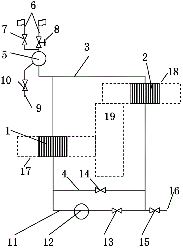
[0039] see figure 1 as shown, figure 1 It is a schematic diagram of the flue gas heating device of the present invention. A flue gas heating device in...


PUM


Abstract

The invention relates to a flue gas heating device and a flue gas heating method. A layout mode is adopted by locating a cooler at a low-location high temperature flue gas inlet duct and locating a heater at a high-location low temperature flue gas outlet duct, and flue gas is heated by making working medium carry out passive flowing between the cooler and the heater. Temperature of the cooler outlet working medium is determined automatically by a vertical height of an arranged drain pipe. Circulating-pump-forced circulation is adopted when the flue gas heating device starts. The working medium is made to flow in medium flow tubes constructed by adopting H-shaped finned tubes and spiral finned tubes or smooth tubes in the cooler and the heater. The invention is advantaged in that the flue gas heating device has the property of stable and safe operation, saves electricity, has great effects on gas-side corrosion prevention and is especially applicable to exhaust heating of flue gas desulfurization.

Description

technical field [0001] The invention belongs to the field of electric power environmental protection, and in particular relates to a flue gas heating device and method. Background technique [0002] In the fields of electric power, metallurgy, chemical industry, building materials, etc., the flue gas with sulfur dioxide generated generally requires flue gas desulfurization treatment in order to meet the emission standards. Flue gas desulfurization technology is mainly based on wet method, so that the flue gas passes through the alkaline solution, and the sulfur dioxide in the flue gas is absorbed by the solution. The temperature of the purified flue gas drops (referred to as low-temperature flue gas), and the amount of water vapor is relatively high. During the discharge process through the chimney, due to the drop in pressure and the drop in heat dissipation temperature, the water vapor is partially converted into liquid droplets, which corrodes the chimney . Chimney anti...

Claims


Application Information

Patent Timeline
IPC IPC(8): F28D15/00
Inventor 舒少辛吕俊复岳光溪
Owner 舒少辛
Features
  • R&D
  • Intellectual Property
  • Life Sciences
  • Materials
  • Tech Scout
  • Unparalleled Data Quality
  • Higher Quality Content
  • 60% Fewer Hallucinations
Learn More