Optical fiber accelerometer
An accelerometer and acceleration technology, which is applied in the direction of using inertial force for acceleration measurement, etc., can solve the problems of large polarization influence and difficulty in implementation, and achieve the effects of good linearity, good stability and low noise.
- Summary
- Abstract
- Description
- Claims
- Application Information
AI Technical Summary
Problems solved by technology
Method used
Image
Examples
Embodiment 1
[0030] like figure 1 As shown, a fiber optic accelerometer includes a light source, a splitter, a polarizer, a phase modulator, a delay fiber, a Faraday rotator, a coupler, an acceleration sensitive head, and a photodetector.
[0031] Among them, the photodetector, light source, splitter, polarizer, phase modulator, delay fiber, and signal processing circuit form the control unit, and the coupler and acceleration sensitive head form the sensing unit.
[0032] The pigtail of the light source is fused with one input fiber of the splitter, the pigtail of the photodetector is fused with the other input fiber of the splitter; the output fiber of the splitter is fused with the polarizer, The polarization-maintaining fiber at the output end of the polarizer and the polarization-maintaining fiber at the input end of the phase modulator are fused at 45°, the output end fiber of the phase modulator is fused with the input end fiber of the delay fiber, and the output end fiber of the del...
Embodiment 2
[0034] like figure 2As shown, a fiber optic accelerometer includes a light source, a splitter, an integrated phase modulator, a polarization beam splitter / combiner, a delay fiber, a Faraday rotator, a coupler, an acceleration sensitive head, and a photodetector.
[0035] Among them, the photodetector, light source, splitter, integrated phase modulator, delay fiber, and signal processing circuit form the control unit, and the coupler and acceleration sensitive head form the sensing unit.
[0036] The pigtail of the light source is fused with the optical fiber at one input end of the splitter, the pigtail of the photodetector is fused with the optical fiber at the other input end of the splitter; the output end of the splitter is fused with the integrated phase modulator, The polarization-maintaining fiber at one output end of the integrated phase modulator is fused with the polarization-maintaining fiber at one input end of the polarization splitter / combiner, and the polarizat...
Embodiment 3
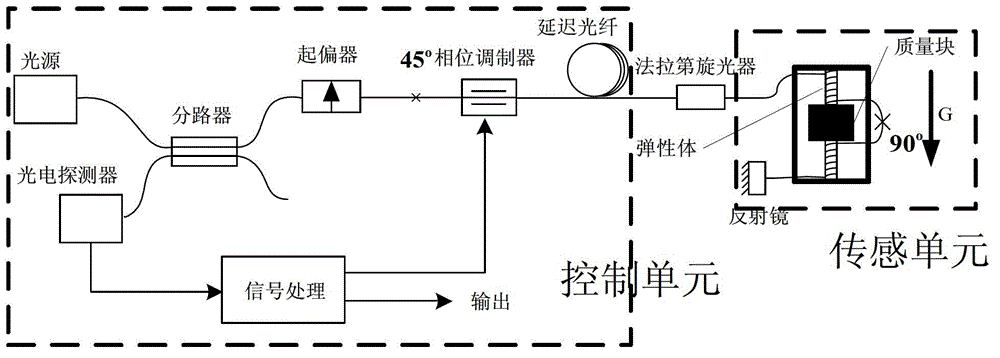
[0038] like image 3 As shown, a fiber optic accelerometer includes a light source, a splitter, a polarizer, a phase modulator, a delay fiber, a Faraday rotator, an acceleration sensitive head, a mirror, and a photodetector.
[0039] Among them, the photodetector, light source, splitter, polarizer, phase modulator, delay fiber, and signal processing circuit form the control unit, and the coupler, acceleration sensitive head, and reflector form the sensing unit.
[0040] The pigtail of the light source is fused with one input fiber of the splitter, the pigtail of the photodetector is fused with the other input fiber of the splitter; the output fiber of the splitter is fused with the polarizer, The polarization-maintaining fiber at the output end of the polarizer and the polarization-maintaining fiber at the input end of the phase modulator are fused at 45°, the output end fiber of the phase modulator is fused with the input end fiber of the delay fiber, and the output end fiber...
PUM
 Abstract
Description
Claims
Application Information
 - Generate Ideas
- Intellectual Property
- Life Sciences
- Materials
- Tech Scout
- Unparalleled Data Quality
- Higher Quality Content
- 60% Fewer Hallucinations
Browse by: Latest US Patents, China's latest patents, Technical Efficacy Thesaurus, Application Domain, Technology Topic, Popular Technical Reports.
© 2025 PatSnap. All rights reserved.Legal|Privacy policy|Modern Slavery Act Transparency Statement|Sitemap|About US| Contact US: help@patsnap.com


