Optical filter switcher

A technology of optical filters and switches, applied in optics, instruments, optical components, etc., can solve the problems of high manufacturing cost and high manufacturing process requirements, and achieve the effect of simple mechanism and small space

Inactive Publication Date: 2012-10-10
SHENZHEN LIBO TECH
View PDF10 Cites 7 Cited by
  • Summary
  • Abstract
  • Description
  • Claims
  • Application Information

AI Technical Summary

Problems solved by technology

There will be hidden dangers of interference with customer organizations, relatively high requirements for manufacturing processes, and relatively high manufacturing costs

Method used


Image

  • Optical filter switcher

Examples


Embodiment Construction

[0016] In order to make the object, technical solution and advantages of the present invention more clear, the present invention will be further described in detail below in conjunction with the accompanying drawings and embodiments.

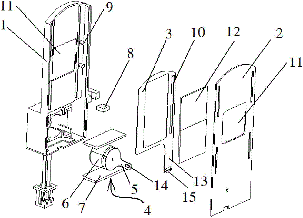
[0017] The invention proposes a filter switcher that uses two pieces of magnetic energy sheets to drive the rotating rocker arm. By changing the direction of the current flowing into the magnetic energy sheets, the magnetic energy sheets can generate magnetic fields in two directions. The generated magnetic fields are the same as the permanent The magnetic field of the magnet repels or attracts, and then realizes the deflection of the permanent magnet in two directions, so that the filter is switched.

[0018] An optical filter switcher, comprising a housing composed of a base 1 and a cover plate 2, a switching pull tab 3 for fixing different optical filters in the housing, and a driving mechanism 4 for driving the switching pull tab 3, character...


PUM


Abstract

The invention relates to an optical filter switcher, which comprises a housing, a switching pulling chip and a driving mechanism, wherein the housing is formed by a base and a cover board; the switching pulling chip is arranged in the housing; and the driving mechanism is used for driving the switching pulling chip. The optical filter switcher is characterized in that the driving mechanism comprises a rotating rocker arm; a rotating shaft of the rotating rocker arm is arranged on a permanent magnet bearing seat; two magnetic energy chips are arranged in parallel on the both sides of the permanent magnet bearing seat and the rotating rocker arm; a magnetic conducting chip is arranged between one magnetic energy chip and the permanent magnet bearing seat; and the magnetic energy chips are thin chips formed by overlaying and compressing a plurality of layers of PCBs (Printed Circuit Board). The magnetic energy chips are ultrathin, occupy a small space and can be used for guiding the rotating rocker arms to take the accurate and in-place fixed-point motion and the rotating rocker arm rotates to pull a connecting position to drive the switching pulling chip so as to finally implement the switching effect on an optical filter. The optical filter switcher has a simple mechanism.

Description

【Technical field】 [0001] The invention relates to the field of image imaging, in particular to an optical filter switcher. 【Background technique】 [0002] In the existing photographing equipment, in order to meet the requirement of photographing in a dark environment, a filter switcher is provided in the photographing equipment. The filter switcher can make the shooting device switch between a daytime shooting mode and a nighttime shooting mode. The filter switch generally includes a visible light glass plate for daytime shooting mode and an infrared light glass plate for nighttime shooting mode. The filter switch generally includes an infrared cut filter for daytime shooting mode, and a white glass for nighttime shooting mode. The filter switcher is generally placed between the lens of the shooting device and the image sensor. When the light is sufficient, the filter switcher sets the infrared cut filter between the lens and the image sensor. between the optical path of ...

Claims


Application Information

Patent Timeline
IPC IPC(8): G03B17/14G02B7/00
Inventor 蒋想正宁浩
Owner SHENZHEN LIBO TECH
Why Eureka
Try Eureka