
Synchronous rectifier control circuit and switch power supply employing same

A synchronous rectification switch and control circuit technology, applied in control/regulation systems, high-efficiency power electronic conversion, electrical components, etc., can solve problems such as secondary side negative current, improve conversion efficiency, eliminate secondary side negative current, and save energy Effect

Active Publication Date: 2012-10-10
SILERGY SEMICON TECH (HANGZHOU) CO LTD
View PDF7 Cites 70 Cited by
  • Summary
  • Abstract
  • Description
  • Claims
  • Application Information

AI Technical Summary

Problems solved by technology

[0005] In view of this, the object of the present invention is to provide a synchronous rectification control circuit and a switching power supply using it to solve the problem in the prior art that the secondary side negative current occurs in order to meet the minimum conduction time of the synchronous rectification switch tube

Method used


Image

  • Synchronous rectifier control circuit and switch power supply employing same
  • Synchronous rectifier control circuit and switch power supply employing same
  • Synchronous rectifier control circuit and switch power supply employing same

Examples


Embodiment Construction

[0041] Several preferred embodiments of the present invention will be described in detail below with reference to the accompanying drawings, but the present invention is not limited to these embodiments. The present invention covers any alternatives, modifications, equivalent methods and schemes made on the spirit and scope of the present invention. In order to provide the public with a thorough understanding of the present invention, specific details are set forth in the following preferred embodiments of the present invention, but those skilled in the art can fully understand the present invention without the description of these details.

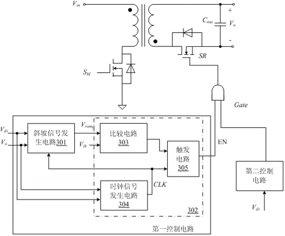
[0042] refer to image 3 , shows the circuit diagram of the first embodiment of a synchronous rectification control circuit according to the present invention. The synchronous rectification control circuit is applied to a flyback converter to control the switching action of the synchronous rectification switching tube SR, which includes ...


PUM


Abstract

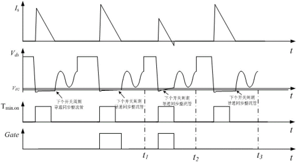
The invention discloses a synchronous rectifier control circuit and a switch power supply employing the same. Whether the conduction time of a synchronous rectifier switch tube meets the requirement of the minimum conduction time in the same switch period and in the conduction interval of a primary side power switch tube can be judged, and the conduction of synchronous rectifier switch tube in the switch period is controlled according to the judgment result, so that secondary side current is completely avoided, electric energy is saved, and the conversion efficiency of the whole power supply circuit is greatly improved.

Description

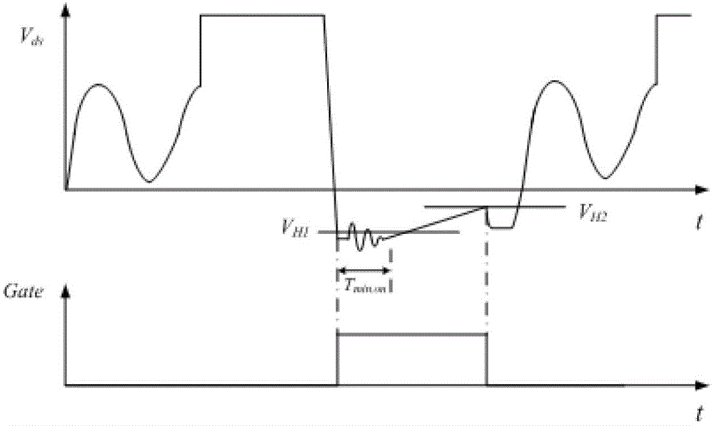
technical field [0001] The invention relates to the field of synchronous rectification control, more specifically, to a synchronous rectification control circuit and a switching power supply using the same. Background technique [0002] The flyback converter has been widely used due to its simple circuit, isolation of input and output voltages, low cost, and less space requirements. However, when the output current is large and the output voltage is low, the secondary The on-state loss and reverse recovery loss of the stage rectifier diode are large, and the efficiency is low. Therefore, the use of synchronous rectification technology and the use of MOSFET power tubes with extremely low on-state resistance to replace the rectifier diode can improve the conversion efficiency of the entire converter. The commonly used synchronous rectification control method is as follows: figure 1 Shown: When the primary side of the flyback converter is turned off, the drain-source voltage s...

Claims


Application Information

Patent Timeline
IPC IPC(8): H02M1/08H02M3/335
CPCY02B70/1475H02M3/33507H02M3/33592Y02B70/10
Inventor 邓建
Owner SILERGY SEMICON TECH (HANGZHOU) CO LTD
Learn More