
Light emitting diode (LED) drive circuit and method without auxiliary winding

A technology of LED drive and auxiliary winding, which is applied in the direction of lamp circuit layout, electric light source, lighting device, etc., can solve the problems of high power supply and drive circuit loss, increase system cost and volume, grid charge loss, etc., to achieve efficiency improvement, Effects of cost reduction and power consumption reduction

Inactive Publication Date: 2012-10-10
SHANGHAI BRIGHT POWER SEMICONDUCTOR CO LTD
View PDF11 Cites 42 Cited by
  • Summary
  • Abstract
  • Description
  • Claims
  • Application Information

AI Technical Summary

Problems solved by technology

[0004] First, the auxiliary winding, rectifier diode D2 and voltage divider resistors increase system cost and size
[0005] Second, the high loss of power supply and drive circuit results in low system efficiency
The power switch MOS transistor M1 is driven by the gate. When M1 is turned off, the gate charge is released to the ground, and the gate charge will be lost in each cycle, so that the driver chip needs more current to complete the power switch MOS transistor. Driven by M1, most of these currents are provided by the auxiliary winding, causing a certain loss

Method used


Image

  • Light emitting diode (LED) drive circuit and method without auxiliary winding
  • Light emitting diode (LED) drive circuit and method without auxiliary winding
  • Light emitting diode (LED) drive circuit and method without auxiliary winding

Examples


Embodiment Construction

[0037] In order to make the object, technical solution and advantages of the present invention clearer, various embodiments of the present invention will be described in detail below in conjunction with the accompanying drawings. However, those of ordinary skill in the art can understand that, in each implementation manner of the present invention, many technical details are provided for readers to better understand the present application. However, even without these technical details and various changes and modifications based on the following implementation modes, the technical solution claimed in each claim of the present application can be realized.

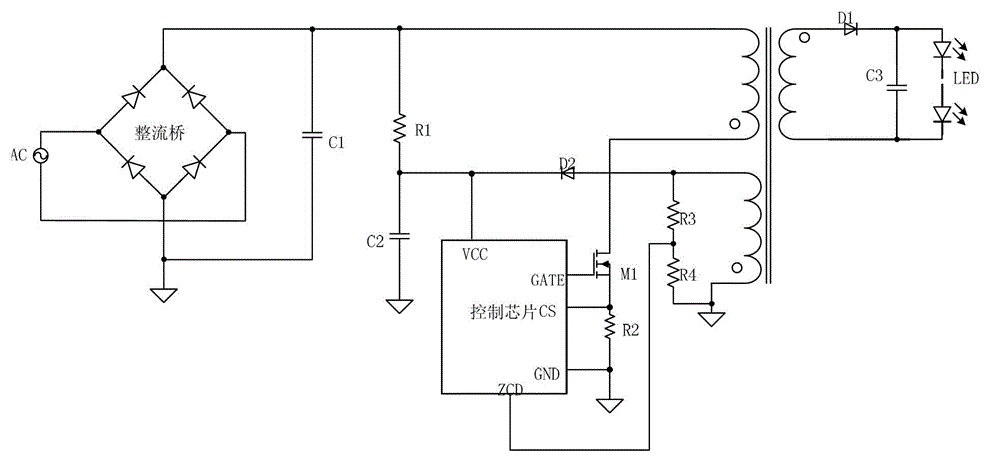
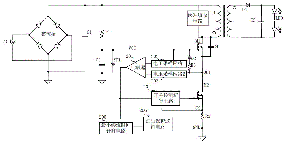
[0038] The first embodiment of the present invention relates to an LED drive circuit without an auxiliary winding. According to this embodiment, the constant current LED drive circuit without an auxiliary winding is useful for figure 1 The drive mode and control mode of the existing drive circuit shown are improved, such as ...


PUM


Abstract

The invention relates to the field of light emitting diodes, and discloses a light emitting diode (LED) drive circuit without an auxiliary winding and an LED drive method without the auxiliary winding. Grid voltage and source voltage of a power switch metal oxide semiconductor (MOS) transistor, which are detected by a voltage sampling network, are compared, and a current zero moment of a freewheel diode D1 is obtained according to a comparison result, so that the switch-off time of the freewheel diode D1 can be determined; average current of an LED load is detected, so constant current drive of an LED is realized; moreover, auxiliary winding is eliminated, so the design of an LED drive power supply is simplified, the size of the LED drive power supply is reduced, and the cost of LED drive power supply is reduced.

Description

technical field [0001] The invention relates to the field of light-emitting diodes (LEDs), in particular to an LED driving circuit without auxiliary windings. Background technique [0002] figure 1 is a simplified schematic diagram of a traditional flyback LED drive circuit. Such as figure 1 As shown, the AC power is rectified by the rectifier bridge and filtered by the capacitor C1 to generate a DC power supply, and the resistor R1 and the capacitor C2 generate a low-voltage DC power to start the control chip. The transformer has three windings, including a primary winding connected between the DC power supply and the drain of the power switch MOS transistor M1, a secondary winding connected between the freewheeling diode D1 and the secondary output capacitor C3, and an auxiliary winding , Connected between diode D2 and circuit ground. When the circuit is started, the auxiliary winding supplies power to the control chip, and the auxiliary winding also provides informati...

Claims


Application Information

Patent Timeline
Patent Type & Authority Applications(China)
IPC IPC(8): H05B37/02
CPCY02B20/42Y02B20/40
Inventor 孙顺根于得水胡黎强杨彪
Owner SHANGHAI BRIGHT POWER SEMICONDUCTOR CO LTD
Features
  • Generate Ideas
  • Intellectual Property
  • Life Sciences
  • Materials
  • Tech Scout
  • Unparalleled Data Quality
  • Higher Quality Content
  • 60% Fewer Hallucinations
Learn More