Numerical control three-dimensional engraving machine

A technology of three-dimensional engraving machine and frame, which is applied in the direction of decorative arts and processing models, and can solve the problems affecting the processing accuracy of workpieces and the deformation of guide rails, and achieve the effects of improving processing accuracy, stable operation, and reasonable overall structure design

Inactive Publication Date: 2012-10-17
NANTONG OUKE CNC EQUIP CO LTD
View PDF8 Cites 7 Cited by
  • Summary
  • Abstract
  • Description
  • Claims
  • Application Information

AI Technical Summary

Problems solved by technology

The "clamping the workpiece after the top is close to the turntable" mentioned here is to complete the clamping of workpieces of different lengths. The "three-dimensional engraving machine" of Chinese Patent No. 200810060107. The cylindrical guide rails arranged in parallel

Method used


Image

  • Numerical control three-dimensional engraving machine
  • Numerical control three-dimensional engraving machine
  • Numerical control three-dimensional engraving machine

Examples


Embodiment Construction

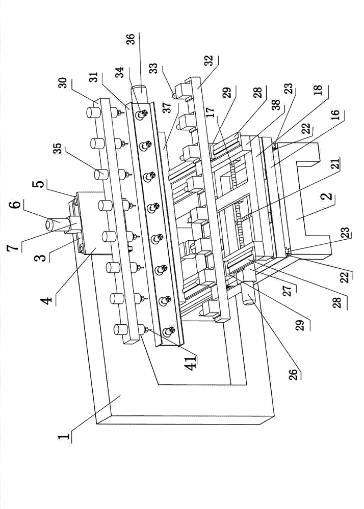
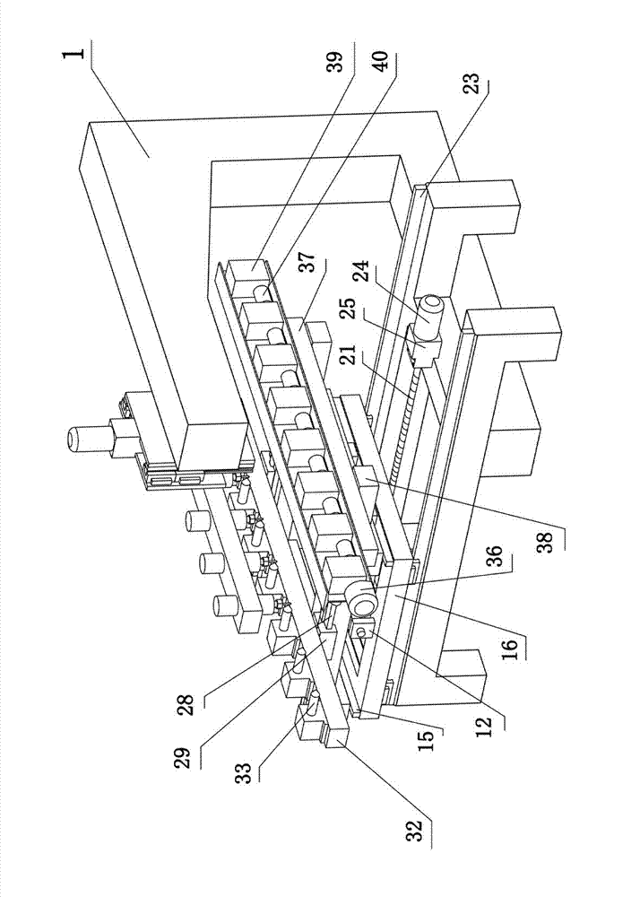
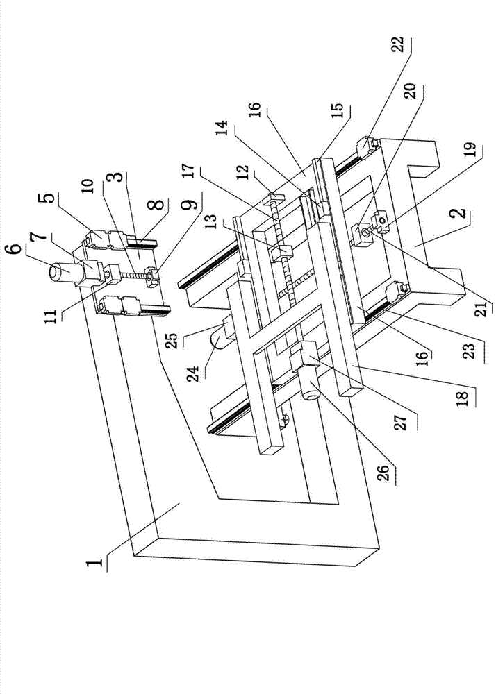
[0029] Refer to attached figure 1 , 2 , 3. A numerically controlled three-dimensional engraving machine includes a frame, a beam, a vertical drive mechanism, a cutter device, a horizontal drive mechanism, a longitudinal drive mechanism, and a workpiece clamping drive mechanism.

[0030] The crossbeam 1 is installed on the top of the frame 2, and the vertical drive mechanism is installed on the crossbeam 1. Described vertical driving mechanism comprises driving motor-6, motor fixing seat-7, slide block-5, vertical guide rail 8, screw mandrel-10, connection block-11, vertical guide rail mounting plate 3 and vertical carriage 4, vertical The guide rail mounting plate 3 is installed on the beam 1, the vertical guide rail 8 is installed on the vertical guide rail mounting plate 3, the vertical guide rail 8 is equipped with a slider 5, and the driving motor 1 6 is installed on the vertical guide rail mounting plate 3 through the motor fixing seat 1 7 Above, the screw mandrel-10 is...


PUM


Abstract

The invention relates to a numerical control three-dimensional engraving machine and belongs to the technical field of wood-working machines. The numerical control three-dimensional engraving machine comprises a frame, a beam, a vertical driving mechanism, a cutter device, a transverse driving mechanism, a longitudinal driving mechanism and a workpiece clamping driving mechanism, wherein the vertical driving mechanism is arranged on the crossbeam and comprises a first driving motor, a first motor fixing seat, a first slide block, vertical guide rails, a first lead screw, a first connecting block, a vertical guide rail mounting plate and a vertical carriage; the cutter device comprises a cutter holder, a cutter and a motor; the longitudinal driving mechanism comprises a longitudinal worktable, longitudinal guide rails, a fourth slide block, a third driving motor, a third lead screw and the like; the transverse driving mechanism comprises a transverse worktable, transverse guide rails, a third slide block, a second driving motor, a second motor fixing seat, a second lead screw, a second connecting plate and a second bearing supporting block; and the workpiece clamping driving mechanism comprises workpiece clamping guide rails, a second cushion block, a second slide block, a tip mounting plate, tips, a first cushion block, a workpiece chuck mounting plate, workpiece chucks, a fourth motor, a reducer and the like.

Description

technical field [0001] The invention relates to a numerically controlled three-dimensional engraving machine, which belongs to the technical field of woodworking machinery. Background technique [0002] In the existing three-dimensional engraving machine technology, when the three-dimensional engraving machine performs horizontal engraving on woodworking workpieces, it is generally completed by the lateral movement of the tool holder equipped with knives. The knives are installed on the water-cooled motor, and the water-cooled motor needs to The tool is driven to rotate at a high speed of more than 20,000 rpm. When engraving a large workpiece or a large amount of engraving, the load on the tool holder is large, which will affect the stability of the operation during the back and forth movement, thereby affecting the machining accuracy of the workpiece. Such as the "three-dimensional engraving machine" of Chinese Patent No. 200810060107.X, the content of the invention [0007] ...

Claims


Application Information

Patent Timeline
IPC IPC(8): B44B1/00B44B1/06
Inventor 张程陈海涛王玉波
Owner NANTONG OUKE CNC EQUIP CO LTD
Why Eureka
Try Eureka