
Rack and pinion steering device

A steering gear and pinion technology, applied in steering gears, steering mechanisms, mechanical steering gears, etc., can solve problems such as thorny operation noise risks, and achieve the effect of simplifying the entire structure

Inactive Publication Date: 2012-10-17
FORD GLOBAL TECH LLC
View PDF6 Cites 3 Cited by
  • Summary
  • Abstract
  • Description
  • Claims
  • Application Information

AI Technical Summary

Problems solved by technology

Furthermore, the steering mechanism in DE 36 13 030 A1 has a troublesome risk of operating noise at relatively large steering angles, since in this case the rack is only guided by the rollers and not by the yoke

Method used


Image

  • Rack and pinion steering device

Examples


Embodiment Construction

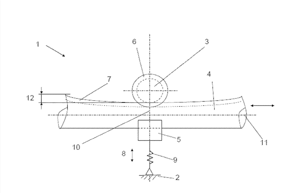
[0041] figure 1 A schematic partial plan view of an embodiment of a rack and pinion steering device 1 according to the invention is shown. Rack and pinion steering 1 comprises a drive pinion 3 rotatably mounted in a steering housing 2, a rack 4 axially movable in the steering housing 2 and a pressure piece 5. The rotatable mounting of the drive pinion 3, and the axially movable mounting of the rack 4 and the pressure piece 5 are done in a conventional manner and are therefore not in figure 1 displayed in detail. Steering gear housing 2 similarly only in figure 1 Schematic indication in.

[0042] In the illustrated embodiment, figure 1 The steering device 1 shown in is part of a steering device (not shown in the figure) of a vehicle, in particular a motor vehicle. For this purpose, the drive pinion 3 is connected for co-rotation with the steering gear end of a steering column which in turn is connected at its other end to a steering wheel by means of which the driver of t...


PUM


Abstract

The invention provides a rack and pinion steering device, comprising a drive pinion (3) and a pressure piece (5), wherein the drive pinion (3) can be rotatably arranged in a steering device shell (2), and is meshed with the tooth part of a rack (4), and can move axially on the steering device shell (2),the pressure piece (5) can be rotatably arranged in the steering device shell (2), and can be loaded on the rack (4) through a spring, and can be used for putting the rack (4) preload to the drive pinion (3),the diameter of the rack (4) increases at least at the tooth part from the central area (10) to the axial tail end of the rack (4),and the rack (4) always contacts the pressure piece (5) only by the sliding friction along the whole process of the rack.

Description

technical field [0001] The invention relates to a rack and pinion steering device. Background technique [0002] Many specific embodiments of rack and pinion steering arrangements are known. They usually have a steering housing for the axial movement of the rack, ie longitudinal movement. A drive pinion rotatably mounted in a steering housing engages teeth on a rack and is connected to the drive pinion for common rotation therewith when the steering column of a vehicle, particularly a motor vehicle steering, is turned The steering column causes lateral displacement of the rack, which in turn causes the steered wheels of the motor vehicle to pivot by means of tie rods and knuckles. The engagement of the drive pinion in the rack is kept free of play by pressing the rack against the drive pinion under spring load by means of a pressure piece which bears against the rack opposite the drive pinion. In this regard, it is also known in the general prior art to adjust the play of...

Claims


Application Information

Patent Timeline
Patent Type & Authority Applications(China)
IPC IPC(8): B62D3/12
CPCB62D3/126B62D3/123
Inventor 托斯滕·克卢格迈克尔·乔治·菲古拉
Owner FORD GLOBAL TECH LLC
Learn More