Depositing apparatus for forming thin film

A technology of deposition equipment and equipment, which is applied in the direction of ion implantation plating, coating, electrical components, etc., can solve the problems of production reduction, impact of component and unit performance, shutdown, etc., and achieve the effect of stable maintenance

Inactive Publication Date: 2012-10-17
SNU PRECISION CO LTD
View PDF5 Cites 4 Cited by
  • Summary
  • Abstract
  • Description
  • Claims
  • Application Information

AI Technical Summary

Problems solved by technology

[0010] However, the amount of deposition sources that can be stored in the source container is limited, thus causing the following problems: the source material for deposition must be frequently refilled, and in all such cases, the deposition apparatus for forming a thin film should be shut down
Therefore, it is inevitable that there will be a problem of lower production due to production stoppages
[0012] In addition, if evaporated material accumulates on the spray holes or internal parts or operating units, it may not only have an impact on the performance of the parts and units, but in severe cases, damage the parts and units

Method used


Image

  • Depositing apparatus for forming thin film
  • Depositing apparatus for forming thin film
  • Depositing apparatus for forming thin film

Examples


Embodiment Construction

[0031] Hereinafter, an exemplary embodiment of a deposition apparatus for forming a thin film according to the present invention will be described with reference to the accompanying drawings.

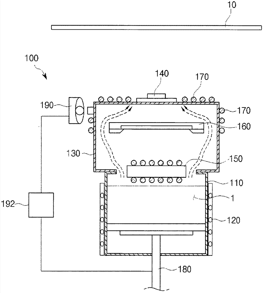
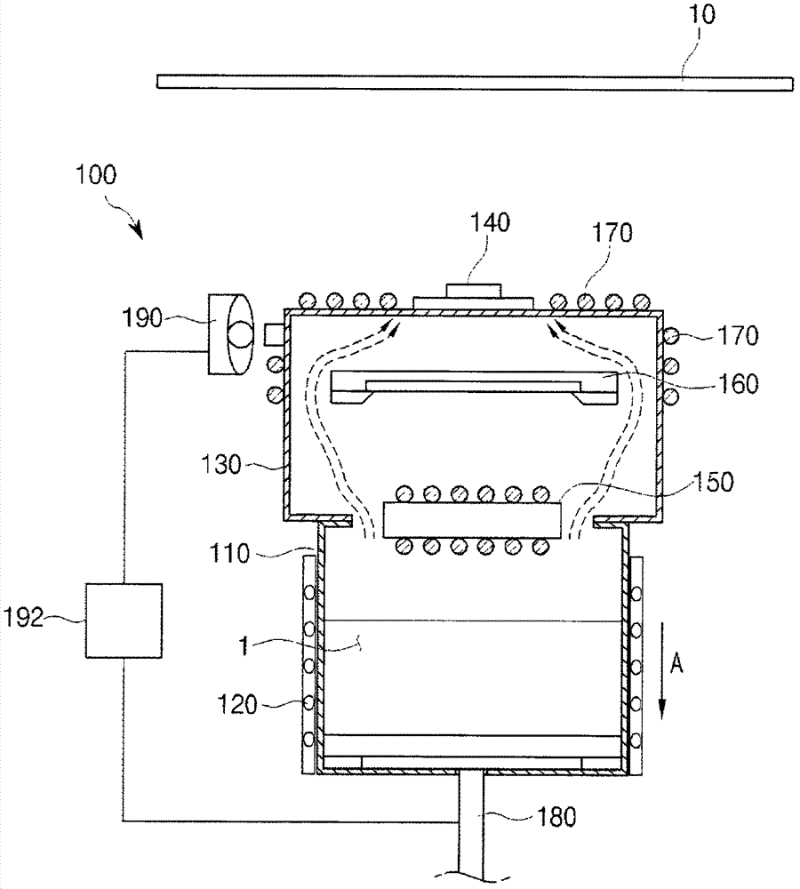
[0032] figure 2 is a schematic diagram of a deposition apparatus for forming a thin film according to an exemplary embodiment, image 3 To show a view of conveying the source material in a direction away from the first heater at figure 2 in deposition equipment used to form thin films.

[0033] see figure 2 and image 3 , the deposition apparatus for forming a thin film in this exemplary embodiment includes a source container 110, a cooler 120, an evaporation chamber 130, an orifice 140, a first heater 150, a blocking plate 160, a second heater 170, a transfer unit 180. A sensor 190 and a controller 192. The deposition device is a device capable of evaporating organic substances and depositing the organic substances on the substrate in the form of a thin film.

[0034] The prese...


PUM


Abstract

Disclosed is a depositing apparatus for forming a thin film, the apparatus including a source container in which a source material to be deposited on a substrate is accommodated in a solid or liquid state; an evaporation chamber which couples and communicates with the source container above the source container, and through which an evaporated source material from the source container passes; a spraying hole which is formed on a top of the evaporation chamber, and sprays upward the evaporated source material passed through the evaporation chamber; a first heater which is provided above the source material inside the evaporation chamber or the source container, and supplies heat to the source material to evaporate the source material accommodated in the source container; and a block plate which is provided above the first heater inside the evaporation chamber, and prevents the source material or foreign materials contained in the source container from being sputtered and attached to the spraying hole while the first heater supplies heat to the source material.

Description

[0001] Cross References to Related Applications [0002] This application claims priority and rights to Korean Patent Application No. 10-2011-0034338 filed with the Korean Intellectual Property Office on April 13, 2011, the entire contents of which are incorporated by reference way incorporated into this article. technical field [0003] The present invention relates to a deposition apparatus for forming a thin film, and more particularly, to a deposition apparatus for forming a thin film in which an organic substance is evaporated and deposited on a substrate in the form of a thin film. Background technique [0004] Organic light-emitting devices are next-generation display devices capable of emitting light by themselves, which are excellent in viewing angle, contrast, response speed, power consumption, etc., compared with liquid crystal display (LCD) devices. [0005] The organic light emitting device includes organic light emitting diodes connected between scan lines an...

Claims


Application Information

Patent Timeline
Patent Type & Authority Applications(China)
IPC IPC(8): C23C14/24C23C14/54
CPCC23C14/26C23C14/12C23C14/544C23C14/24C23C14/564H10K71/00
Inventor 赵晃新宋基哲郑胜哲安祐正
Owner SNU PRECISION CO LTD
Why Eureka
Try Eureka