Hanging bracket for quick construction on inner wall of spherical tank

A spherical tank and fast technology, which is applied to the scaffolding of house structure support, house structure support, house structure support, etc., can solve the problems that the equipment cannot stand and unfold effectively, waste of manpower, material resources, and low labor efficiency, so as to reduce construction Effects of cost and quantity of materials, improvement of construction efficiency, and shortening of construction period

Inactive Publication Date: 2012-10-17
于学恭
View PDF4 Cites 0 Cited by
  • Summary
  • Abstract
  • Description
  • Claims
  • Application Information

AI Technical Summary

Problems solved by technology

Due to the spherical structure of the inner wall, personnel and equipment cannot stand and unfold effectively during construction. Usually, a full house of scaffolding is used for construction, which is manifested in the use of a huge number of scaffolds. It often takes more than 20 workers to complete the assembly and takes the same time to dismantle. , wasting a lot of manpower and material resources
Low labor efficiency and low safety

Method used


Image

  • Hanging bracket for quick construction on inner wall of spherical tank
  • Hanging bracket for quick construction on inner wall of spherical tank
  • Hanging bracket for quick construction on inner wall of spherical tank

Examples


Embodiment 1

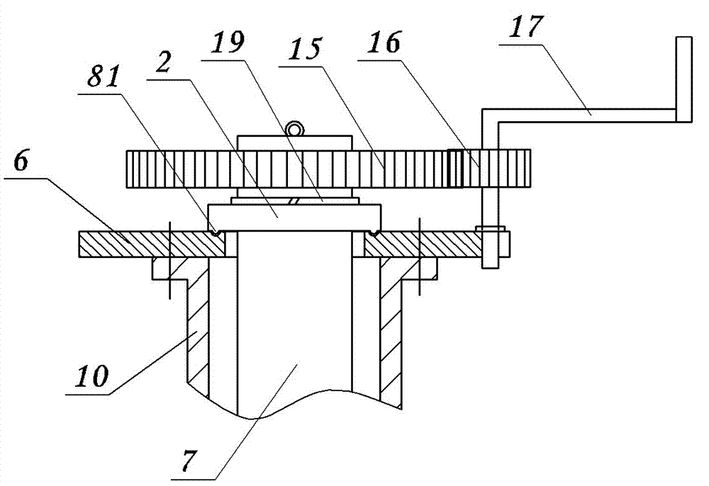
[0027] There are various forms of the rotating mechanism, and the rotating mechanism of the present embodiment can be found in figure 2 , including a central rotating shaft 7, on which a flange plate 6 fixedly installed with the central manhole is set, and a limit plate 2 is also set on the central rotating shaft 7, and the limit plate 2 is located on the side of the flange plate 6 upper side. The limit plate 2 and the central shaft are fixed by a circlip 19, and a contact surface matching mechanism 8 is arranged between the limit plate 2 and the flange 6, that is, the lower surface of the limit plate 2 and the upper surface of the flange 6 A ring-shaped convex-concave matching structure 81 is adopted on the contact surface of the surface.

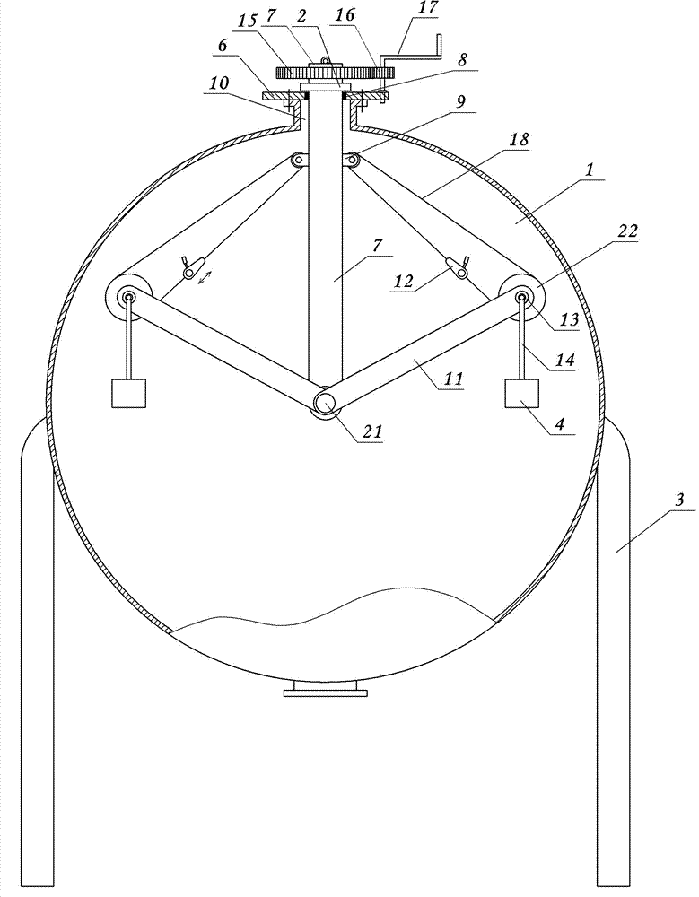
[0028] The upper part of the central rotating shaft 7 (located inside the sphere) is provided with hinged ears 9, and the lower end is provided with a supporting rotating shaft 21, which is located at the center of the sphere, and two or...

Embodiment 2

[0033] Embodiment 3: The drawings are not drawn, and the content is basically the same as Embodiment 1, and the similarities will not be repeated. The difference is: the rocker is replaced with a controllable small motor.

Embodiment 3

[0034] Embodiment four: see figure 1 , image 3 , Figure 4 and Figure 7 , the content is basically the same as that of Embodiment 1, and the similarities will not be repeated. The difference is that the central hole of the flange 6 adopts an inverted tapered structure, and a tapered wear-resistant pad 82 is set in the inverted tapered hole. Shape wear-resistant pad 82 upper ends contact with the limit disk lower surface.


PUM


Abstract

The invention relates to a hanging bracket for quick construction on the inner wall of a spherical tank. A rotating mechanism is fixed on a central manhole at the spherical top of the spherical tank and comprises a central rotating shaft, the lower end of the central rotating shaft is positioned at the spherical center of the spherical tank and is respectively articulated with at least two hanging arms, and the tail end of each hanging arm is provided with a hanging basket and a tightening mechanism. According to the invention, the manhole at the center of the upper part of the spherical tank is taken as a rotation center, the hanging baskets can rotate for 360 degrees and stop rotating through the control on the central rotating shaft, the hanging baskets can go up and down and rotate or stop going up and down and rotating through starting a lever block of the tightening mechanism, and no other auxiliary component is welded on the oil tank, so that the structural performance of an oil tank body is not changed, and no bracket such as scaffold is used; and the hanging bracket is simple in structure and reasonable in design. According to the hanging bracket, the stability and safety are improved, the construction period is shortened greatly, and a large quantity of scaffolds and labor costs are reduced; and the hanging bracket can be reutilized, thus having remarkable economic benefits and being suitable for popularization and implementation.

Description

technical field [0001] The invention relates to an auxiliary tool for anticorrosion treatment of the inner wall of a steel spherical tank, in particular to a rapid construction hanger for the inner wall of a spherical tank. Background technique [0002] Various types of spherical storage tanks are widely used in petrochemical, metallurgy, municipal storage and transportation industries. Larger volume, usually 500M 3 —5000M 3 , its inner surface is subjected to anti-corrosion, installation and maintenance and flaw detection operations. Due to the spherical structure of the inner wall, personnel and equipment cannot effectively stand and unfold during construction. Usually, a full house of scaffolding is used for construction, which is manifested in the use of a huge number of scaffolds. It often takes more than 20 workers to complete the assembly and takes the same time to dismantle. , wasting a lot of manpower and material resources. Labor efficiency is low and safety is...

Claims


Application Information

Patent Timeline
Patent Type & Authority Applications(China)
IPC IPC(8): E04G3/28E04G3/34
Inventor 于学恭
Owner 于学恭
Why Eureka
Try Eureka