Continuous pipeline tripping device

A technology for pipelines and oil pipelines, applied in the field of continuous pipeline lifting and lowering devices, can solve the problems of limited selection of pipeline diameter range, difficult operation at the wellhead, and difficult operation at the wellhead, so as to improve the construction success rate, avoid hard contact, reduce The effect of risk factors

Active Publication Date: 2012-10-17
PETROCHINA CO LTD
View PDF8 Cites 33 Cited by
  • Summary
  • Abstract
  • Description
  • Claims
  • Application Information

AI Technical Summary

Problems solved by technology

[0004] 1. The hydraulic injection head is independent and movable as a whole, and it needs to be hoisted and installed during construction, which is difficult to operate at the wellhead
[0005] 2. The occlusal device that holds the pipeline tightly is a pure metal block that directly occludes the pipeline. When the pipeline is lifted, it is easy to bite the pipeline
[0006] 3. The transmission part can only be threaded, and the operation at the wellhead is difficult, and the diameter range of the pipeline is limited

Method used


Image

  • Continuous pipeline tripping device
  • Continuous pipeline tripping device
  • Continuous pipeline tripping device

Examples


Embodiment Construction

[0058] In order to make the object, technical solution and advantages of the present invention clearer, the implementation manner of the present invention will be further described in detail below in conjunction with the accompanying drawings.

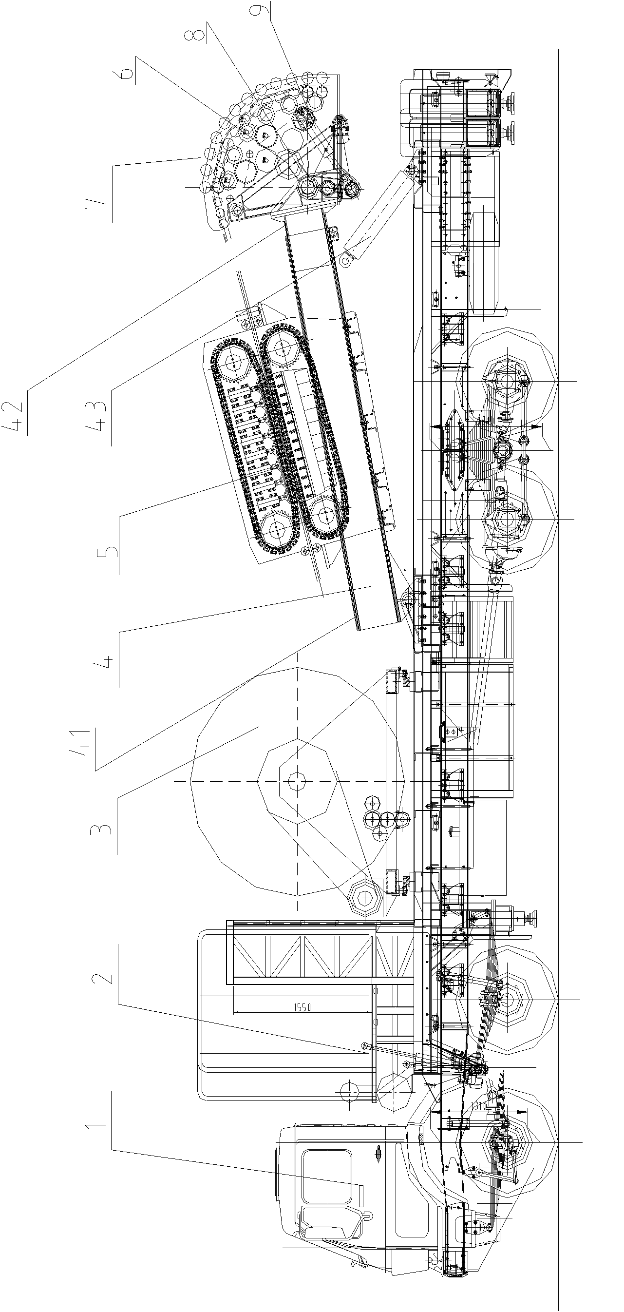
[0059] The structure of the lifting device of the present invention is as follows: figure 1 As shown, it is mainly composed of the following parts: vehicle system 1, operation control room 2, roller retraction and discharge system 3, flat traction system, guide injection system, hydraulic power system, blowout prevention system and auxiliary system, etc.

[0060] The functional and technical requirements of each component of the lifting device:

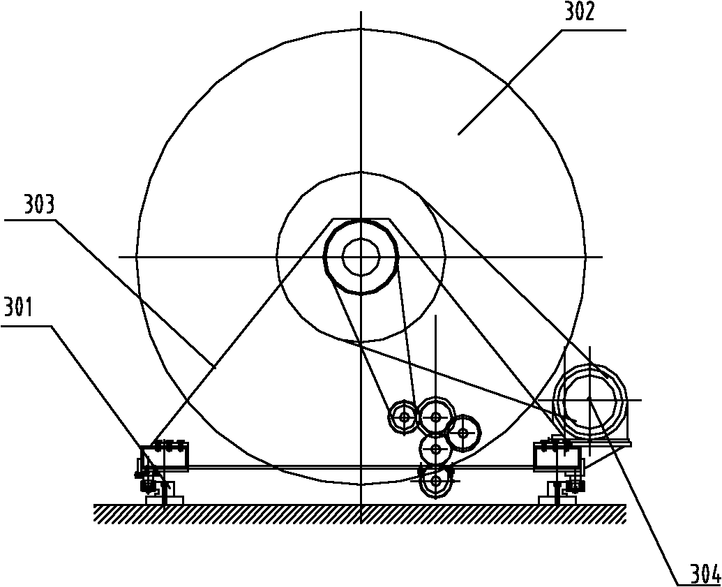
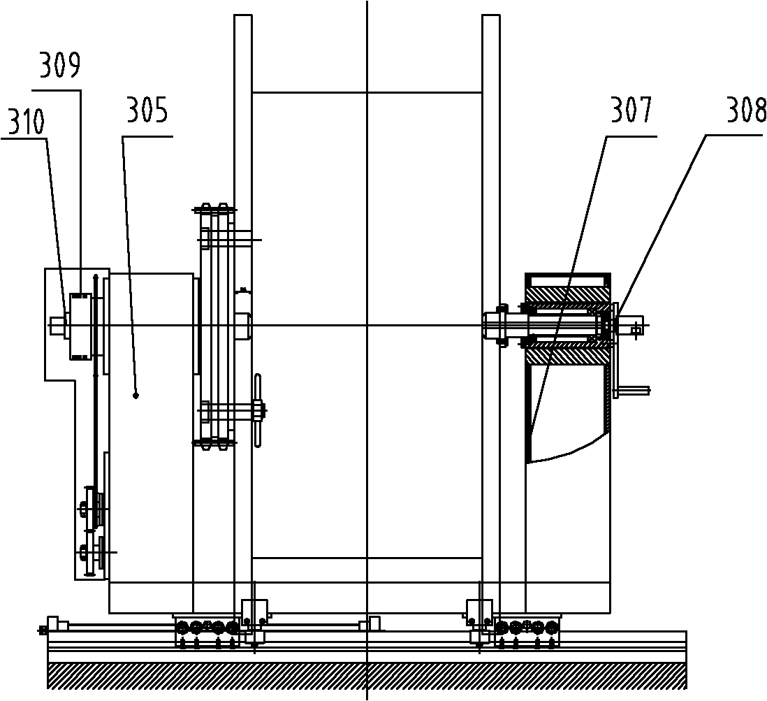
[0061] (1) Shaftless take-up and discharge system: It is mainly used for rewinding and unwinding, and makes the tubing lined up on the reel; it can assist pulling the tubing when necessary. Hydraulic drive, chain and gear drive winding and pipe arrangement, maximum rewinding force 5t, maximum...


PUM


Abstract

The invention discloses a continuous pipeline tripping device, comprising a rotating drum retracting, laying and releasing system, a guided injection system, a traction system, and a hydraulic power system used for supplying power for the above systems. The rotating drum retracting, laying and releasing system comprises a rotating drum, a cable laying device and a guide rail, wherein the guide rail is fixed on an underpan of a vehicle system, the rotating drum is in a sliding connection with the guide rail through a rotating drum supporting seat, the cable laying device is fixed on one side of the rotating drum, the rotating drum is driven to move along the guide rail by the cable laying device, thereby realizing the arrangement of an oil pipeline on the rotating drum. The traction system comprises a double-arm crane and a flat track frictional transmission device. When the rotating drum rotates, the oil pipeline on the rotating drum passes through the flat track frictional transmission device and a guided injection head in sequence to enter into an oil well. According to the invention, a fast connection with the mouth of the well is guaranteed, the operational process of site construction is simplified, the damage of pipelines is prevented, and the success rate of construction is increased.

Description

technical field [0001] The invention relates to the field of oil production monitoring in the petroleum industry, in particular to a continuous pipeline hoisting device, which is a device for testing, unblocking and gas lifting using the coiled tubing. Background technique [0002] At present, the coiled tubing operation machine used in the testing field in various domestic oil fields is a mobile hydraulically driven equipment for lifting and transporting coiled tubing imported from abroad. It is mainly composed of hydraulic injection head, drum, wellhead blowout preventer It is composed of truck-mounted crane, hydraulic power system, telescopic control room and self-propelled chassis. [0003] In the process of realizing the present invention, the inventor finds that the prior art has at least the following disadvantages: [0004] 1. The hydraulic injection head is independent and movable as a whole. It needs to be hoisted and installed during construction, which is diffic...

Claims


Application Information

Patent Timeline
Patent Type & Authority Applications(China)
IPC IPC(8): E21B19/22
Inventor 孙守国杨立强杨建平赵鹏杨志祥郑南方张福兴李强洪梅陈俊丁亚军程云龙范先曙
Owner PETROCHINA CO LTD
Why Eureka
Try Eureka