
Method for measuring sight line stabilizing accuracy of photoelectric sight-stabilizing system

A photoelectric stable pointing and stable precision technology, applied in the field of optical measurement, can solve the problems of high cost, error, guarantee, etc.

Active Publication Date: 2012-10-17
中国兵器工业第二0五研究所
View PDF6 Cites 11 Cited by
  • Summary
  • Abstract
  • Description
  • Claims
  • Application Information

AI Technical Summary

Problems solved by technology

In this method, the acquisition object of the digital camera sensor is a star-point hole image with a certain spectral distribution (non-monochromatic), so in order to obtain a higher image quality, the positive group lens and the negative group lens are separated, and a special lens is selected. Dispersive positive group lens material corrects the secondary spectrum, so this method is more expensive
In addition, the phase correlation registration method used in this method has high computational complexity and requires better workstation performance. At the same time, the registration method requires that the difference between the star point hole images in the multiple images involved in the correlation operation should not be too large. Otherwise, it will cause errors, but the non-uniformity of the light source, measurement beam power fluctuations, detector noise, environmental changes and other issues will make it difficult to guarantee this condition in actual measurement, affecting the accuracy and reliability of measurement results

Method used


Image

  • Method for measuring sight line stabilizing accuracy of photoelectric sight-stabilizing system
  • Method for measuring sight line stabilizing accuracy of photoelectric sight-stabilizing system
  • Method for measuring sight line stabilizing accuracy of photoelectric sight-stabilizing system

Examples


Embodiment Construction

[0060] The present invention will be described in further detail below in conjunction with the accompanying drawings and preferred examples.

[0061] The concrete implementation process of the present invention comprises the following operation steps:

[0062] The first step is to install the object under test

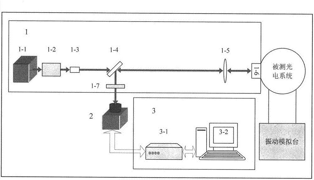
[0063] Such as figure 1 As shown in Fig. 1, the electro-optical stabilization system under test is fixed on the vibration simulation table with steel bolts and clamps. Turn on the vibration simulation table, set the vibration mode of the simulation table to fixed frequency mode, and set the working state to vibration stop state. In this embodiment, the vibration simulation platform is a large-scale vibration simulation experiment device from UD Company of the United States, and its vibration sweep frequency range is 2 Hz to 500 Hz.

[0064] The second step is to build the measuring device

[0065] The method for measuring line-of-sight stability accuracy of the pre...


PUM


Abstract

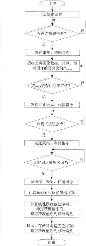
The invention discloses a method for measuring the sight line stabilizing accuracy of a photoelectric sight-stabilizing system, and belongs to the technical field of optical measurement. The method is characterized by comprising the following steps that: a plane reflector is fixed on an inner ring frame of the photoelectric sight-stabilizing system to be measured, the photoelectric sight-stabilizing system to be measured is in a vibration state, a measuring laser beam is subjected to strength stabilization, spatial filtering and collimation and then irradiates the plane reflector, a complementary metal oxide semiconductor (CMOS) camera transmits a light spot image sequence of a reflected light beam imaged on a target surface to an image recording and processing system, and the image recording and processing system performs a series of processing on the light spot image sequence to obtain a light spot center-of-mass coordinate sequence, a stabilizing accuracy value sequence and stabilizing accuracy value sequence standard deviation, so that the stabilizing accuracy is measured. By the method, the high-accuracy measurement of the sight line stabilizing accuracy of the photoelectric sight-stabilizing system is realized; and the method can be popularized to the fields of measurement of the stabilizing accuracy of a gun control system and the like, and is wide in application prospect.

Description

technical field [0001] The invention belongs to the technical field of optical measurement, and mainly relates to a method for measuring the stable precision of a line of sight, in particular to a method for measuring the stable precision of a line of sight for a photoelectric system of a moving carrier. Background technique [0002] The photoelectric stabilized aiming system is widely used in high-tech weaponry and equipment systems, and is a key technology to realize the precise strike of high-tech weaponry and equipment. Modern airborne, vehicle-mounted, and ship-borne optoelectronic weapons and equipment all put forward high requirements for the stable accuracy of the line of sight in the optoelectronic stabilized sight system. In the actual combat environment, the electro-optical stabilization system will inevitably be disturbed by various frequency vibrations in the external environment. At this time, the stability of the line of sight is an important evaluation index ...

Claims


Application Information

Patent Timeline
IPC IPC(8): G01M11/02
Inventor 杨斌黎高平王乐杨冶平杨鸿儒袁良岳文龙吕春莉薛战理汪建刚闫晓宇韩占锁谢毅
Owner 中国兵器工业第二0五研究所
Learn More