
RFID (Radio Frequency Identification )-based grid positioning system and method

A positioning method and grid technology, applied in the field of RFID-based grid positioning system, can solve the problems of not being widely used, limited, and unable to achieve positioning, and achieve the effects of convenient application, reduced impact, and strong anti-interference ability

Inactive Publication Date: 2012-10-17
SICHUAN YANCHENG COMM TECH
View PDF7 Cites 20 Cited by
  • Summary
  • Abstract
  • Description
  • Claims
  • Application Information

AI Technical Summary

Problems solved by technology

[0004] 1. The basic principle of GPS positioning is to measure the distance between the known satellite and the user's receiver, and then combine the data of multiple satellites to know the specific position of the receiver; the disadvantage is that the GPS receiver must receive 4 The signal of more than one (including) GPS satellites can be used to determine the position. Once the signal is not received, the positioning will not be realized.
[0005] 2. The disadvantage of A-GPS technology positioning is the same as that of GPS. It must receive more than 4 satellite signals to locate
[0006] 3. gpsOne is only applicable to CDMA network, which is too limited to be widely used
[0008] These positioning technologies are mainly used in space or on the ground. It is difficult to achieve good results when the indoor signal is weak or in deep mountains and forests. Therefore, it is necessary to implement RFID-based grid positioning technology.

Method used


Image

  • RFID (Radio Frequency Identification )-based grid positioning system and method
  • RFID (Radio Frequency Identification )-based grid positioning system and method
  • RFID (Radio Frequency Identification )-based grid positioning system and method

Examples


Embodiment 1

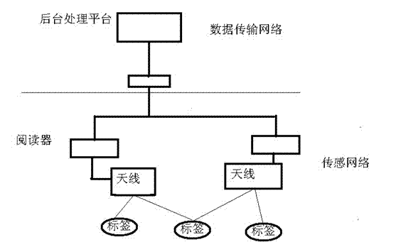
[0044] Such as figure 1 As shown, the RFID-based grid positioning system includes two networks, namely the sensor network and the data transmission network. The sensor network is generally composed of RFID readers and electronic tags, which can be regarded as a reader / electronic tag array set by the user. The target to be positioned carries a reader or tag, and the reader / electronic tag array receives instructions from the server, obtains the characteristic information (such as signal strength) of the target to be positioned according to the server's instructions, and stores it in the reader middle. The data transmission network includes a server and connections between the server and each reader. The server generates instruction signals according to the user's needs and transmits them to the sensor network. After the reader in the sensor network obtains the information related to the target to be located, it feeds back to the server through the data transmission network. ...


PUM


Abstract

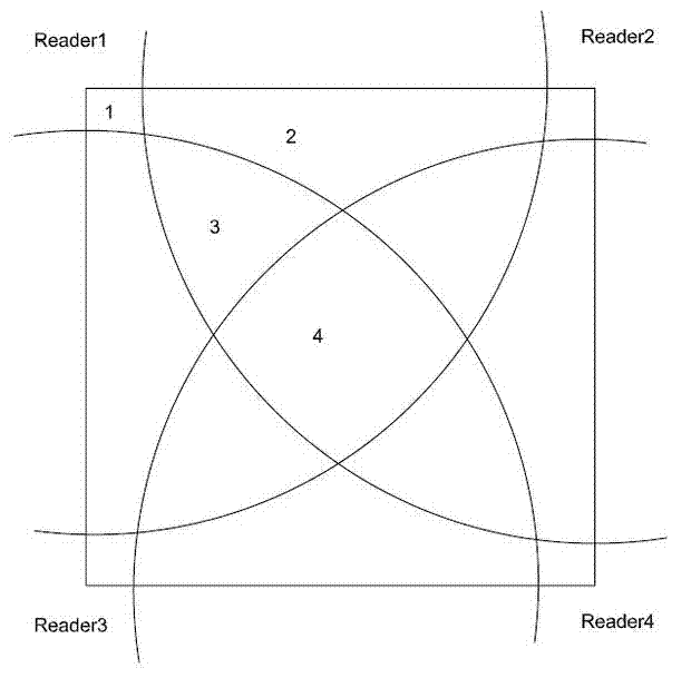
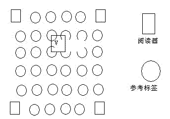
The invention discloses an RFID (Radio Frequency Identification )-based grid positioning system and method. The system comprises a RFID reader-writers for obtaining information of an object to be positioned through an antenna, electronic tags for recording related information of the object to be positioned, and a server, wherein the server transmits an instruction signal to the RFID reader-writers and the electronic tags according to the requirement of a user, so as to obtain a coordinate of an electronic tag of the object to be positioned. The positioning method comprises the steps of establishing a two-dimensional matrix space from a area to be positioned, wherein four RFID reader-writers (respectively formed by a plurality of virtual grid units) are arranged at four corners of the two-dimensional matrix space, and each virtual grid unit comprises two or four virtual reference tags; and judging detection ranges of the RFID reader-writers so as to obtain a preliminary position of the object to be positioned, and then positioning the object to be positioned according to the virtual reference tags in a preliminary position. According to the scheme disclosed by the invention, the non-contact operation is adopted, and thus the application is relatively convenient, the sensitivity is good, and objects in high-speed motion can be identified, and a plurality of objects can be identified and read simultaneously.

Description

technical field [0001] The invention relates to the technical field of RFID positioning, in particular to an RFID-based grid positioning system and method. Background technique [0002] So far, the theory of radio frequency identification technology has been enriched and perfected. Single-chip electronic tags, multi-electronic tag reading, wireless readable and writable, long-distance identification of passive electronic tags, and radio frequency identification technologies and products adapted to high-speed moving objects are becoming a reality and moving towards application. RFID technology has a broad application space: many enterprises and organizations have used RFID technology in access control systems and identification systems; RFID technology can also be used in property protection, car tracking, parking lots and highway bridge billing; logistics RFID technology is widely used in the industry, and intelligence will be fully realized from product production, produc...

Claims


Application Information

Patent Timeline
IPC IPC(8): G01S5/02G06K17/00H04L29/08
Inventor 张军
Owner SICHUAN YANCHENG COMM TECH
Learn More