Near-field sound source positioning method

A sound source localization and near-field technology, used in localization, measurement devices, instruments, etc.

Inactive Publication Date: 2012-10-17
SHAOXING UNIVERSITY
View PDF0 Cites 26 Cited by
  • Summary
  • Abstract
  • Description
  • Claims
  • Application Information

AI Technical Summary

Problems solved by technology

[0004] The present invention aims at the shortcomings that the existing near-field sound source localization method requires multi-dimensional parameter search or high-order statistic calculation, and requires that the array element interval Δ must be less than 1/4 wavelength, and provides a method that does not require multi-dimensional parameter search or h

Method used


Image

  • Near-field sound source positioning method
  • Near-field sound source positioning method
  • Near-field sound source positioning method

Examples


Embodiment 1

[0074] Using a uniform linear array composed of multiple pairs of speed sensors can improve the estimation performance of parameters through aperture expansion; in addition, there is no need for multi-dimensional parameter search or calculation of high-order statistics, and automatic pairing of parameter estimation can be realized.

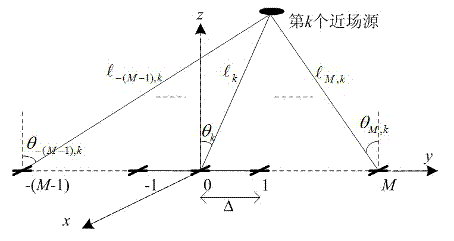
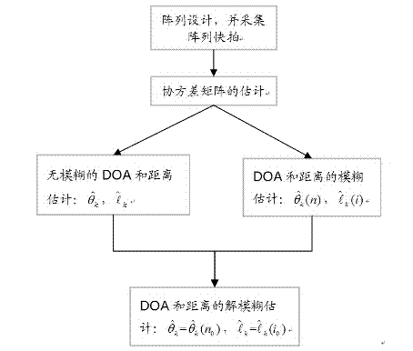
[0075] Near-field sound source localization methods, such as figure 1 As shown, the following steps are taken:

[0076] Step 1: Set up a uniform linear array

[0077] Set up a uniform linear array (K<2M) composed of 2M array elements. The array element interval is Δ, and each array element is an array composed of a pair of speed sensors, pointing to the y-axis and the z-axis respectively.

[0078] Step 2: Build a signal model

[0079] Consider K near-field, narrow-band, incoherent sound source signals incident on the above-mentioned uniform linear array, -π / 2m,k ≤π / 2 means the DOA of the kth near-field source signal relative to the mth array el...

Embodiment 2

[0123] Embodiment 2 (experimental example)

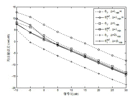
[0124] Set a uniform linear array containing 16 speed sensors (ie M=4), and the signal sampling frequency is f samp =15MHz, and consider two near-field sound sources (k 1 , k 2 ), whose parameters are: ω 1 =0.4πrad / s and ω 2 =0.5πrad / s (that is, the wavelength is λ 1 =100m and λ 2 =80m), θ 1 =25°, θ 2 = 40°, l 1 =2.5λ 1 , l 2 =3.0λ 2 . N=400 snapshots are used to simulate the experimental results of near-field source location. The simulation results are the statistical results of 500 Monte Carlo experiments, such as image 3 , Figure 4 , Figure 5 , Figure 6 .

[0125] in, image 3 , 4 The relationship between the root mean square estimation error of the DOA of the two signal sources and the signal ratio is given, where image 3 for the signal k 1 , Figure 4 for the signal k 2 . We consider three different cases of array element spacing Δ: Δ=λ min / 4, Δ=λ min and Δ=2λ min , where λ min =min{λ 1 ,λ 2}...


PUM


Abstract

The invention relates to the technical field of array signal processing and discloses a near-field sound source positioning method for estimating a direction of arrival (DOA) of a near-field sound source signal and signal source distance by adopting a speed sensor array. The method has the advantages that a high-order accumulated value is not required to be calculated, so that relatively low operation amount is achieved; automatic paring in parameter estimation can be realized; a distance between two array elements does not need to be limited in the 1/4 wavelength range; the aperture of the array can be expanded by increasing the distance between two array elements; and therefore, the parameter estimation precision of an algorithm can be improved.

Description

technical field [0001] The invention relates to the technical field of array signal processing, in particular to a near-field sound source localization method for estimating DOA and signal source distance of a near-field sound source signal by using a velocity sensor array. Background technique [0002] The underwater acoustic vector sensor consists of 2 to 3 speed sensors plus an optional pressure sensor. The velocity sensor is orthogonally oriented and can measure the acoustic velocity components in the Cartesian coordinate system separately. In the past few decades, the acoustic vector sensor has received extensive attention in both theory and engineering applications. The vector array composed of acoustic vector sensors has become an important tool for underwater sound source localization, and many effective algorithms have been proposed. However, these algorithms are mainly for far-field signals. When the signal source is close to the array and located in its near-fiel...

Claims


Application Information

Patent Timeline
IPC IPC(8): G01S5/18
Inventor 刘兆霆
Owner SHAOXING UNIVERSITY
Why Eureka
Try Eureka