Hollow cube-corner prism optical delay line device with endogenous scale light source

A corner cube prism and ruler technology, applied in the field of optical instruments, can solve problems such as difficulty in guaranteeing the posture of the right-angle prism and incident light, difficulty in obtaining a delayed signal with stable return light ratio, complicated calibration process, etc., to achieve fast measurement speed and excellent installation process Simple, low-precision effects

Active Publication Date: 2013-12-18
TIANJIN SUOWEI ELECTRONICS TECH
View PDF8 Cites 3 Cited by
  • Summary
  • Abstract
  • Description
  • Claims
  • Application Information

AI Technical Summary

Problems solved by technology

However, the change in the length of the delay line is caused by the rotation of the square prism. The delay length and the rotation angle are not linear, and calibration is required. The calibration process is complicated. The calibration result has a lot to do with the uniformity of the rotation of the square prism.
[0005] The delay line technology in the above instruments, such as the delay line in the patent US5673096A, is affected by the linear motion speed, needs to start and stop acceleration and deceleration processing, the measurement speed is slow, only one parameter is measured at a time, and other external measurement devices are required for the measurement of the moving distance; the patent In the delay line technology mentioned in US20090268209A, when the incident light beam enters the rotating square prism, it needs to go through eight times of transmission and reflection, and the return light ratio (ratio of the output light to the incident light power) is seriously reduced, which reduces the signal-to-noise ratio
[0006] For the delay line technology in the above two instruments, the incident light needs to be transmitted and reflected inside the right-angle prism or square prism. Due to the influence of the refractive index of the prism material, the dispersion effect is aggravated. The posture is not easy to guarantee and requires precise adjustment, and the longer the delay line is, the more difficult it is to obtain a delayed signal with a stable light return ratio

Method used


Image

  • Hollow cube-corner prism optical delay line device with endogenous scale light source
  • Hollow cube-corner prism optical delay line device with endogenous scale light source
  • Hollow cube-corner prism optical delay line device with endogenous scale light source

Examples


example 1

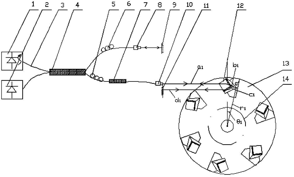
[0032] The light source of the ruler adopts a narrow-line light source, and a DFB (Distributed Feed Back) laser with a wavelength of 1310nm and a bandwidth of 10MHz is selected. Of course, other narrow-line light sources that meet the requirement that the coherence length is greater than the optical path change of the delay line can be selected. The light source of the scale passes through a single-mode fiber And the 2×2 fiber coupler is divided into two optical fibers, the first of which passes through the polarization controller P 1 After adjusting to linear polarized light, it enters the optical collimator Z 1 , becomes collimated light and shoots vertically to the plane reflector FX, and passes through the plane reflector F 1 After reflection, return to the original path, pass through the 2×2 fiber coupler, and enter the photoelectric sensor. The second path passes through the polarization controller P 2 After being adjusted to linear polarization, it enters the waveleng...

example 2

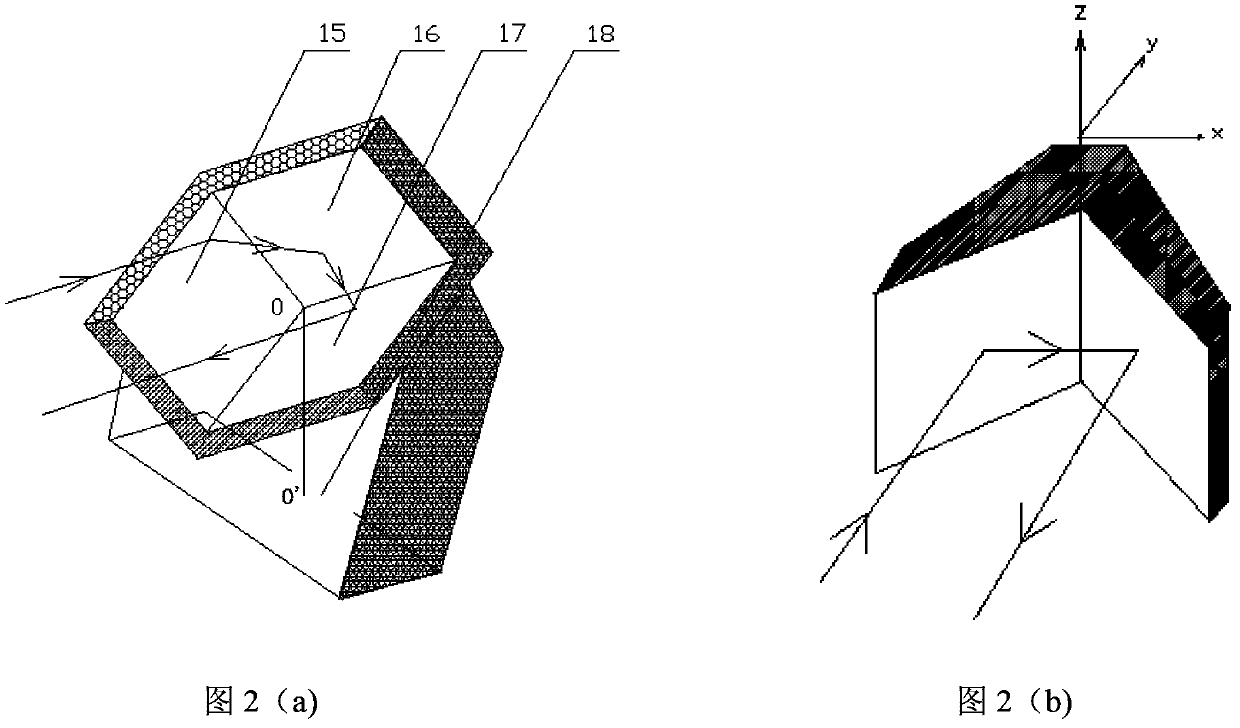
[0040] Compared to hollow corner cubes, such as figure 2 As shown in (b), a simplified example that is easy to think of is a hollow right-angle prism, which is made of two pieces of flat glass or other materials with high-precision working surfaces. Angle of incident light, the rotation of the hollow rectangular prism around the z axis will not affect the coplanar parallel relationship between the outgoing light and the incident light, but the rotation of the hollow rectangular prism around the y axis and the x axis will affect the coplanar relationship between the outgoing light and the incident light face parallel relationship.

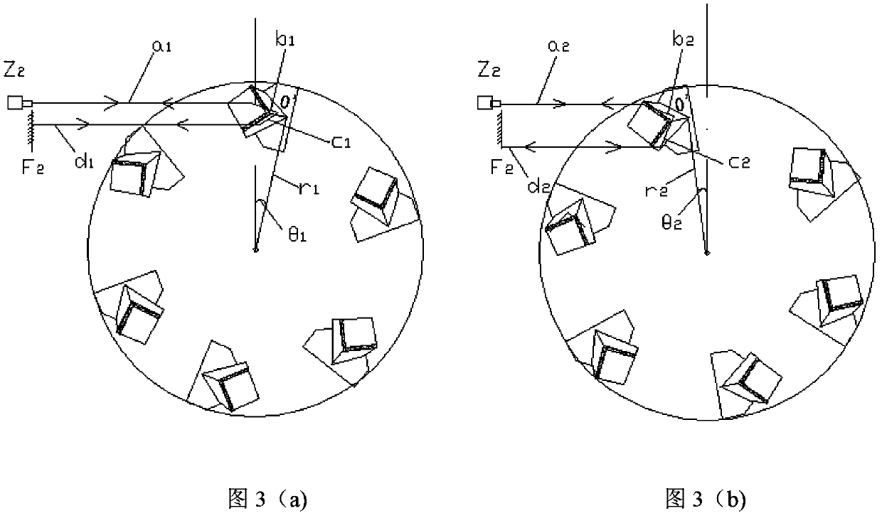
[0041] When using this device, the signal light source passes through the polarization controller P along the single-mode fiber 2 , wavelength division multiplexer, collimator Z 2 Together to the hollow rectangular prism, we can add a fiber coupler to the single-mode optical fiber to expand the number of optical fibers, so as to connect the photo...


PUM


Abstract

The invention relates to a hollow cube-corner prism optical delay line device with an endogenous scale light source. The hollow cube-corner prism optical delay line device comprises a scale light source, a photoelectric sensor, an optical fiber coupler, a wavelength division multiplexer, collimators Z1 and Z2, plane reflecting mirrors F1 and F2, polarization controllers P1 and P2, a single-mode optical fiber, a rotary disk, hollow cube-corner prisms and a motor, wherein a scale light source signal is divided into two paths of light signals by the optical fiber coupler; the first path of light signals passes through the polarization controller P1 and the collimator Z1, is emitted to the plane reflecting mirror F1, returns along the same road and is received by the photoelectric sensor; and the second path of light signals passes through the polarization controller P2, the wavelength division multiplexer and the collimator Z2, is emitted to the hollow cube-corner prisms which are uniformly distributed on the rotary disk along the circumference, is guided for 180 DEG and then emitted to the plane reflecting mirror F2 and returns along the same road, and a returned signal is received by the photoelectric sensor and interferes with the first path of signals. The hollow cube-corner prism optical delay line device is simple in installation process and high in measuring speed, and signal to noise ratio and measuring accuracy are improved.

Description

technical field [0001] The invention relates to the field of optical instruments, in particular to ophthalmic optical equipment of optical delay lines, in particular to a hollow corner cube optical delay line device with an endogenous scale light source. Background technique [0002] The optical delay line is an optical device that changes the optical path or phase. In the measuring instruments that use the principle of interference, the optical delay line needs to change the optical path or phase, so that the optical path of the measurement optical path and the optical path of the reference optical path meet the interference conditions. to complete the measurement. Most of the optical interferometry techniques that have appeared in recent years are based on the principle of broadband light interference, and can be roughly divided into two categories: one uses partial coherence interferometer (PCI), and the other uses low coherence reflectometry (Low Coherence Refl. ectomet...

Claims


Application Information

Patent Timeline
Patent Type & Authority Patents(China)
IPC IPC(8): G02B17/08G02B26/06G01J9/02G01B11/06A61B3/10
Inventor 赵培泉王雪乔王健发
Owner TIANJIN SUOWEI ELECTRONICS TECH
Why Eureka
Try Eureka