
Control method and device

A control method and control device technology, applied in the communication field, can solve problems such as complex control circuits

Active Publication Date: 2012-10-17
HUAWEI DIGITAL POWER TECH CO LTD
View PDF3 Cites 11 Cited by
  • Summary
  • Abstract
  • Description
  • Claims
  • Application Information

AI Technical Summary

Problems solved by technology

[0006] The embodiment of the present invention provides a control method and device, to a certain extent, solves the problems in the prior art that the control circuit is complex and needs to be slowed down during state switching, and realizes the smooth switching of the three topological states

Method used


Image

  • Control method and device
  • Control method and device
  • Control method and device

Examples


Embodiment Construction

[0022] In order to make the objectives, technical solutions, and advantages of the embodiments of the present invention clearer, the technical solutions in the embodiments of the present invention will be described clearly and completely in conjunction with the accompanying drawings in the embodiments of the present invention. Obviously, the described embodiments It is a part of the embodiments of the present invention, not all the embodiments. Based on the embodiments of the present invention, all other embodiments obtained by those of ordinary skill in the art without creative work shall fall within the protection scope of the present invention.

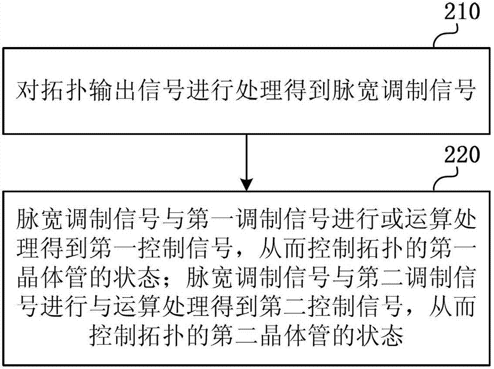
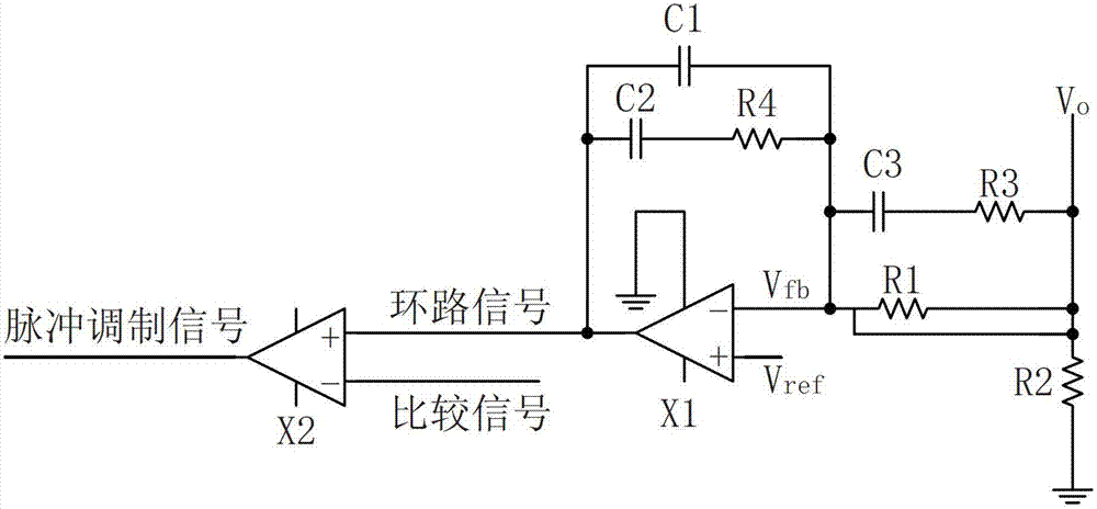
[0023] The present invention discloses a control method and device. The pulse width modulation signal is obtained by processing the output signal of the BUCK-BOOST topology, the pulse width modulation signal and the first modulation signal are ORed to obtain the first control signal, and the pulse The wide modulation signal and the se...


PUM


Abstract

The embodiment of the invention relates to a control method and device which are applied to BUCK-BOOST topology. The method concretely comprises the following steps: processing topological output signal to obtain a pulse width modulation signal; performing OR operation on the pulse width modulation signal and a first modulation signal to obtain a first control signal so as to control the state of a first transistor of the topology; performing AND operation on the pulse width modulation signal and a second modulation signal to obtain a second control signal so as to control the state of a second transistor of the topology. Therefore, the method realizes three topological states and smooth handover, and simultaneously the control circuit is relatively simple; and the control range is enlarged and the control precision is improved.

Description

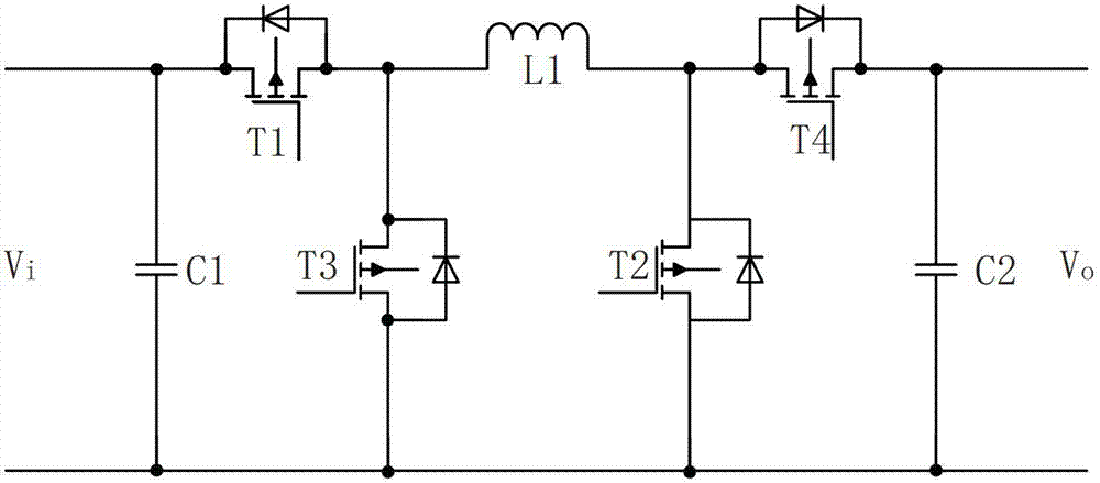
Technical field [0001] The present invention relates to the field of communication technology, in particular to a control method and device. Background technique [0002] As the power of routers, enterprise network equipment, and single boards increase, some high-power frame-type equipment requires the direct current / direct current (DC / DC) voltage stabilizing module in the system to support flexible configuration. Meet customer investment requirements and power distribution requirements in the computer room. In order to improve the conversion efficiency of the DC / DC voltage regulator module, the single-inductor buck-boost (BUCK-BOOST) topology is a topology that supports the DC / DC voltage regulator module to achieve high efficiency. [0003] figure 1 It is a circuit diagram of a single-inductor BUCK-BOOST topology in the prior art. Such as figure 1 As shown, Metal-Oxide-Semiconductor Field-Effect Transistor (MOSFET) field-effect transistor T1, MOSFET field-effect transistor T3 an...

Claims


Application Information

Patent Timeline
IPC IPC(8): H02M3/158
CPCH02M3/157H02M3/158H02M3/1582H02M1/36
Inventor 黄锦波
Owner HUAWEI DIGITAL POWER TECH CO LTD
Learn More