
Wireless micro-display system

A technology of microdisplays and displays, applied in static indicators, instruments, televisions, etc., can solve the problems of image quality loss, high power consumption, large delay, etc., to reduce wires and extension lines, low transmission power, high resolution rate effect

Active Publication Date: 2012-10-17
南京昀光科技有限公司
View PDF4 Cites 13 Cited by
  • Summary
  • Abstract
  • Description
  • Claims
  • Application Information

AI Technical Summary

Problems solved by technology

At the same time, it can make up for the problems of large delay, image quality loss and high power consumption of existing wireless image transmission display devices

Method used


Image

  • Wireless micro-display system
  • Wireless micro-display system
  • Wireless micro-display system

Examples


Embodiment 1

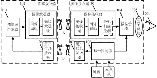
[0025] see figure 1 , the wireless microdisplay system includes an image sending end and an image receiving end, and data exchange is performed between the image sending end and the image receiving end through a wireless communication protocol; the image sending end is used to generate an image source, and the image source generator (101) Connecting the image transmitter (102) and the user information receiver (108), the image source generator (101) is used to generate images, and the image transmitter (102) is used to transmit the images generated by the image source generator (101) through wireless The user information receiver (108) is used to receive user information from the image receiving end wirelessly; the image receiving end is used to receive and display the image source, and the image receiver (103) and the microdisplay (104) are connected to the optical system (105) and a display controller (106) are connected to a microdisplay (104) and a user information transmi...

Embodiment 2

[0027] This embodiment is basically the same as Embodiment 1, and the special features are as follows:

[0028] In the above-mentioned wireless microdisplay system, the image sending end sends the image data to the image receiving end through the wireless communication protocol A, and the wireless communication protocol A is UWB, WHDI, WirelessHD, WiFi, WiMAX, WiDi or LTE; the image receiving end passes The wireless communication protocol B sends the user information back to the image sending end, and the wireless communication protocol B is infrared, bluetooth, WiFi, WiMAX or other wireless communication protocols for transmitting small batches of data. The user information transmitter and receiver provide the user with data return function, so that the user can control the system on the image receiving end (ie micro-display), such as sending touch screen signals, on-screen display control signals, display content control signals, Or the camera image input signal of the low-r...

Embodiment 3

[0034] Embodiment three: the present embodiment is basically the same as embodiment one and embodiment two, and the special features are as follows:

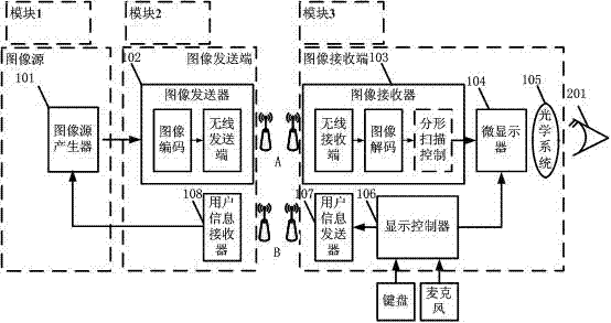
[0035] see image 3 , the above-mentioned wireless micro-display system is composed of module 1, module 2 and module 3. Each module has an independent function, and module 1 is an image source, which is composed of an image source generator (101). Module 2 is an image sending end, consisting of an image sender (102) and a user information receiver (108). Module 3 is an image receiving end, which is composed of an image receiver (103), a microdisplay (104), an optical system (105), a display controller (106) and a user information transmitter (107).


PUM


Abstract

The invention relates to a wireless micro-display system. The wireless micro-display system comprises an image transmitting terminal and an image receiving terminal, wherein data exchange is performed between the image transmitting terminal and the image receiving terminal through a wireless communication protocol; the image transmitting terminal is used for generating an image source and is formed by connecting an image transmitter with a user information receiver through an image source generator; the image source generator is used for generating an image; the image transmitter is used for transmitting the image generated by the image source generator in a wireless way; the user information receiver is used for receiving user information from the image receiving terminal in the wireless way; the image receiving terminal is used for receiving and displaying the image source and is formed by connecting the image receiver with an optical system through a micro displayer and with a micro displayer user information transmitter through a display controller; the image receiver is used for receiving the image transmitted by the image transmitter in the wireless way; the micro displayer is used for displaying image data on a micro screen; the optical system is used for enlarging the image displayed on the micro screen for observation; the display controller is used for generating control information required by the micro screen; and the user information transmitter is used for transmitting user information to the image transmitting terminal in the wireless way. The dependence of a system on a physical wire is reduced, the mobility of equipment is enhanced, and the power consumption and the image quality loss are reduced.

Description

technical field [0001] The invention relates to a microdisplay system based on wireless data transmission, which includes an image sending end and an image receiving end. Background technique [0002] Among many display products, micro-display is a relatively special product form, and it is generally defined as a display whose screen diagonal size is less than 3.3cm. The physical size of the microdisplay itself is very small, and the pixel pitch is only about ten microns, but it can realize super large screen display through the optical system. In consumer electronics, microdisplays can be applied to the expansion of mobile devices such as head-mounted video players, head-mounted home theaters, head-mounted virtual reality simulators, head-mounted game consoles, head-mounted medical diagnostic systems, and mobile phones Displays and micro-projectors can be used in individual combat systems, weapon targeting systems, infrared night vision devices, and air force helmet system...

Claims


Application Information

Patent Timeline
Patent Type & Authority Applications(China)
IPC IPC(8): H04N7/26G09G3/20H04N19/42
Inventor 季渊何林奇黄海浪黄舒平冉峰徐美华
Owner 南京昀光科技有限公司
Learn More