Novel lower limb joint mechanism of reclining-type Lower limb rehabilitation robot

A technology for rehabilitation robots and lower limbs, applied in gymnastics equipment, sports accessories, etc., can solve problems such as the length and limitation of transmission timing belts, and the inability to achieve good consistency in the movements of human lower limbs and mechanisms, achieving good consistency and facilitating separate optimization , the effect of preventing abnormal situations

Active Publication Date: 2012-10-24
INST OF AUTOMATION CHINESE ACAD OF SCI
View PDF5 Cites 19 Cited by
  • Summary
  • Abstract
  • Description
  • Claims
  • Application Information

AI Technical Summary

Problems solved by technology

The advantage of the former is that the axes of the joints of the lower limbs of the human body and the joint axes of the lower limbs are basically the same, which can make the mechanism and the lower limbs of the human body maintain consistent movements; The timing belt is long, which inevitably causes the mechanism to vibrate during operation, which greatly affects the smooth operation and normal use of the equipment.
The advantage of the latter is that the joint mechanism realizes local drive, and the motor directly drives the rotating nut of the ball screw, which avoids the vibration problem caused by too long transmission chain, and the use of the ball screw can achieve higher precision and better performance. stability; however, the existing joint mechanisms using this method are in the design of the crank-slider mechanism (such as the literature "Metrailler P, Blanchard V, Perrin I, Brodard R, Frischknecht R, Schmitt C, Fournier J, Bouri M and C

Method used


Image

  • Novel lower limb joint mechanism of reclining-type Lower limb rehabilitation robot
  • Novel lower limb joint mechanism of reclining-type Lower limb rehabilitation robot
  • Novel lower limb joint mechanism of reclining-type Lower limb rehabilitation robot

Examples


Embodiment Construction

[0019] In order to make the object, technical solution and advantages of the present invention clearer, the present invention will be described in further detail below in conjunction with specific embodiments and with reference to the accompanying drawings.

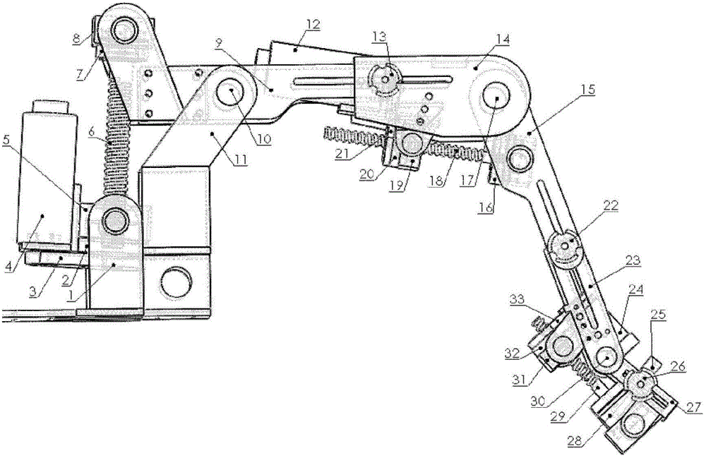
[0020] The design goal of the lower limb joint mechanism of the novel sitting-horizontal lower limb rehabilitation robot disclosed by the present invention is: the focus of hip joint design is to make the drive motor power smaller and produce better mechanical properties, and the maximum torque of the hip joint is 150NM. The rotation angle ranges from 0° to 70°; the focus of the design of the knee joint is to make the size of the overall mechanism smaller, the maximum torque of the knee joint is 65NM, and the range of rotation angle is 50° to 170°; The size of the mechanism is small, the maximum torque of the ankle joint is 5NM, and the rotation angle ranges from -40° to 40°.

[0021] figure 1 It is a structural diagram ...


PUM


Abstract

The invention discloses a novel lower limb joint mechanism of a reclining-type Lower limb rehabilitation robot. The mechanism comprises three joint mechanisms including a hip joint mechanism, a knee joint mechanism and an ankle joint mechanism, and three connection rod mechanisms including a thigh link mechanism, a crus link mechanism and an ankle-high link mechanism. The hip joint mechanism, the knee joint mechanism and the ankle joint mechanism can be conveniently and respectively optimized by adopting different slider-crank mechanisms. Rotary nut-type ball screws are respectively adopted by all the joint mechanisms to form sliding pairs of the slider-crank mechanisms; all the joint mechanisms are respectively provided with a pull pressure sensor which can be used for indirectly measuring the torque of a corresponding joint; each joint is provided with a direct-current motor which can be used for independently driving the corresponding joint mechanism; and the direct-current motors are respectively provided with a position sensor. All the joint mechanisms respectively have a center of rotation, and the thigh link mechanism, the crus link mechanism and the ankle-high link mechanism are adjustable in length, so that the lower limb joint mechanism can be kept highly consistent with lower limbs of a human body.

Description

technical field [0001] The invention relates to the technical field of medical devices, in particular to a novel lower limb joint mechanism of a sitting and lying lower limb rehabilitation robot. Background technique [0002] At present, there are more and more researches on sitting and lying lower limb rehabilitation robots in China, and many related patents have also been proposed. For sitting and lying lower limb rehabilitation robots, the lower limb mechanism is one of the most critical mechanisms. The joint mechanism in the lower limb mechanism is the most critical mechanism of the lower limb mechanism. The lower body consists of three joints: hip, knee, and ankle. Considering that the sitting and lying lower limb rehabilitation robot should be able to achieve flexible training trajectory planning and provide passive, active and power-assisted training, these three joints need to be driven by their own drive motors, and force (or torque) should be configured at each j...

Claims


Application Information

Patent Timeline
IPC IPC(8): A63B23/04
Inventor 侯增广王卫群李鹏峰程龙边桂彬谢晓亮张峰谭民柳会
Owner INST OF AUTOMATION CHINESE ACAD OF SCI
Why Eureka
Try Eureka