Fluidized bed reactor

A fluidized bed reactor and reaction tube technology, applied in chemical/physical/physical chemistry nozzle reactors, chemical instruments and methods, inorganic chemistry, etc. Difficulty maintenance, heavy weight of the fluidized bed reactor, etc., to achieve the effect of preventing pollution, easy installation and maintenance, and easy installation and maintenance

Inactive Publication Date: 2012-10-24
SILICONVALUE
View PDF3 Cites 2 Cited by
  • Summary
  • Abstract
  • Description
  • Claims
  • Application Information

AI Technical Summary

Problems solved by technology

Therefore, the fluidized bed reactor capable of producing polysilicon in batches is very heavy and bulky, which makes it difficult to assemble, install and maintain the fluidized bed reactor

Method used


Image

  • Fluidized bed reactor
  • Fluidized bed reactor
  • Fluidized bed reactor

Examples


Embodiment Construction

[0036] Preferred embodiments of the present invention will be described in detail below with reference to the accompanying drawings.

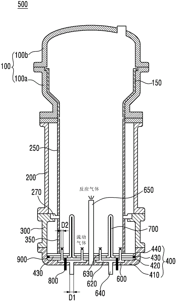
[0037] figure 1 A fluidized bed reactor of an embodiment of the invention is shown. As shown in the figure, the fluidized bed reactor 500 of the embodiment of the present invention includes a top cover 100 , a first main body part 200 , a second main body part 300 and a bottom part 400 .

[0038] The top cover 100 is connected to the first body part 200 and has a diameter larger than that of the first reaction tube 250 of the first body part 200 . When the gas and fine particles in the fluidized bed reactor 500 pass through the top cover 100 from the first reaction tube 250, the flow velocity of the gas and fine particles decreases due to the increase in diameter.

[0039] Therefore, the post-processing burden of exhausted gas or fine particles is reduced. The inner wall of the top cover 100 may be composed of an inorganic material that is n...


PUM

PropertyMeasurementUnit
diameteraaaaaaaaaa

Abstract

A fluidized bed reactor is disclosed. The fluidized bed reactor includes a reaction pipe,a flowing-gas supply unit configured to supply flowing gas to an internal space of the reaction pipe by controlling the supply of the flowing gas independently,and a reaction gas supply unit configured to supply reaction gas to the internal space of the reaction pipe.

Description

technical field [0001] The present invention relates to fluidized bed reactors. Background technique [0002] High-purity polysilicon is widely used as a material that can be used in semiconductor devices and solar cells. To produce such polysilicon, a silicon precipitation method is used, in which silicon is deposited by thermal decomposition and hydrogen reduction reaction of a silicon-containing reaction gas. [0003] For mass production of polysilicon, fluidized bed reactors larger in size and height than those used in laboratories are required. Therefore, the fluidized bed reactor capable of producing polysilicon in batches is very heavy and has a large volume, which makes assembly, installation and maintenance of the fluidized bed reactor difficult. [0004] Therefore, research is in full swing for a fluidized bed reactor that is easy to assemble, install and maintain, and can produce polysilicon in large quantities. Contents of the invention [0005] The object o...

Claims


Application Information

Patent Timeline
Patent Type & Authority Applications(China)
IPC IPC(8): B01J8/24C01B33/021C30B28/14
CPCC01B33/027B01J8/1818B01J8/1827C01B33/03B01J2208/00415B01J2208/00398B01J8/18B01J19/26C01B33/035C30B29/06
Inventor 丁允燮金根镐尹汝均金镇成
Owner SILICONVALUE
Why Eureka
Try Eureka