Anaerobic fluidized bed reactor

An anaerobic fluidized bed and reactor technology, which is applied in the field of anaerobic fluidized bed reactors, can solve the problems of low mass transfer efficiency and achieve the effects of thorough reaction, clear effluent and increased residence time

Active Publication Date: 2012-10-24
CHINA PETROLEUM & CHEM CORP +1
View PDF5 Cites 20 Cited by
  • Summary
  • Abstract
  • Description
  • Claims
  • Application Information

AI Technical Summary

Problems solved by technology

However, the use of fixed fillers as the carrier for biofilm

Method used


Image

  • Anaerobic fluidized bed reactor

Examples


Example Embodiment

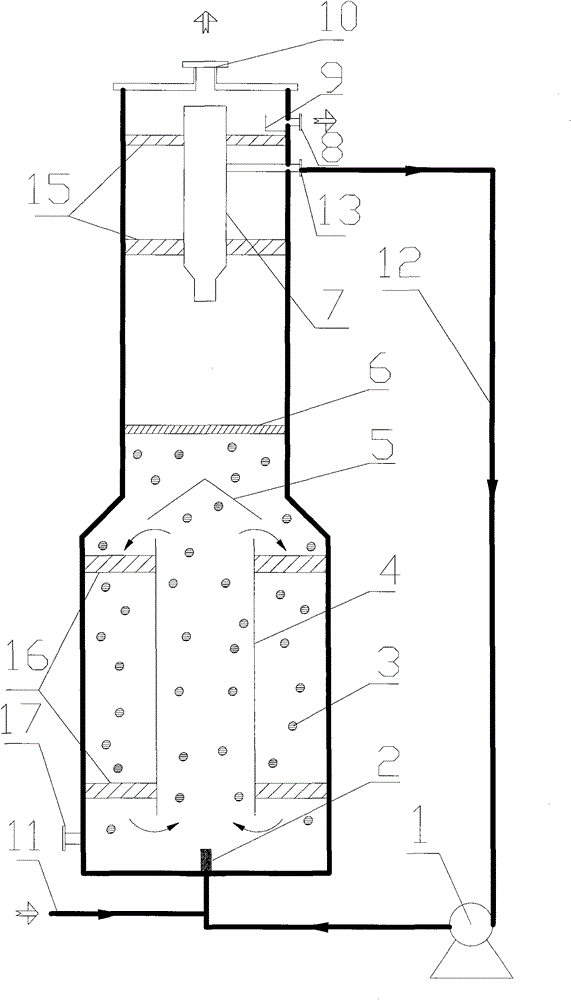
[0029] As shown in the figure, the figure is a schematic structural diagram of an anaerobic biological fluidized bed reactor of the present invention. The anaerobic fluidized bed reactor is a two-stage cylinder with a thin upper part and a thick lower part. The upper part and the lower part are connected by a tapered transition section. The reactor is provided with a complete mixing reaction zone and In the plug flow reaction zone, a jet nozzle 2 is installed at the center of the bottom of the anaerobic fluidized bed reactor, a filler 3 is installed in the complete mixing reaction zone, and a guide tube 4 is arranged 100-300mm directly above the jet nozzle 2, namely The vertical distance between the bottom of the guide tube 4 and the top of the jet nozzle 2 is 100-300 mm. The guide tube 4 is connected to the anaerobic fluidized bed reactor through the guide tube support 16. A cap 5 is provided at 40~200mm directly above the guide tube 4, and a liquid-solid separator 6 is provid...


PUM


Abstract

The invention discloses an anaerobic fluidized bed reactor, characterized in that: the anaerobic fluidized bed reactor is a two-section cylinder which is thin above and thick below, the upper section is connected with the lower section through a taper transition section, a completly mixed reaction zone and a plug flow reaction zone are arranged in the reactor from bottom to top, a guide cylinder is arranged in the completly mixed reaction zone, a cover hood is arranged above the guide cylinder, a liquid-solid separator is arranged in the plug flow reaction zone, a three-phase separator is arranged above the liquid-solid separator, the water outlet of the three-phase separator is successively connected with a circulating pump and a jet nozzle through a circulating pipeline, and a water inlet pipeline is connected with the jet nozzle. By using outer circulation to drive inner circulation, the efficiency of the reactor is greatly raised.

Description

Technical field [0001] The invention belongs to the field of sewage biochemical treatment and relates to an anaerobic fluidized bed reactor. Background technique [0002] Anaerobic treatment technology has become an energy-saving technology of general concern at home and abroad due to its lack of violent gas, low sludge output and recyclable biogas. At present, the common anaerobic reactors mainly include the following types: upflow anaerobic sludge bed reactor (UASB), anaerobic biological filter (AF), expanded granular sludge bed reactor (EGSB) and internal circulation reactor (IC) and other equipment. There is no mature anaerobic fluidized bed used in industrial production. [0003] During the operation of the up-flow anaerobic sludge bed (UASB) reactor, wastewater enters the reactor from the bottom of the reactor at a certain flow rate through the water distribution system, and the water is distributed evenly by the water distributor, and the water flows through the sludge bed...

Claims


Application Information

Patent Timeline
IPC IPC(8): C02F3/28
Inventor 刘献玲何庆生李佳铮
Owner CHINA PETROLEUM & CHEM CORP
Why Eureka
Try Eureka