Single-pump hydraulic control loop of key drilling action of cutting drill rig

A control circuit and key technology, applied in the automatic control system of drilling, the driving device for drilling in the wellbore, mechanical equipment, etc., can solve the problems of large single-turn feed of the drill bit, low rotary resistance, and stuck pipe. , achieve the effect of shortening the operation cycle time, improving the automatic adaptability and preventing the drill bit from slipping

Active Publication Date: 2012-10-24
SUNWARD INTELLIGENT EQUIP CO LTD
View PDF9 Cites 15 Cited by
  • Summary
  • Abstract
  • Description
  • Claims
  • Application Information

AI Technical Summary

Problems solved by technology

[0003] However, the cutting drilling rig hydraulic system based on the improvement and development of the hydraulic system of the excavator has the advantages of simplicity and ease of operation, which shortens the development cycle of the cutting drilling rig hydraulic system, but this system has inherent limitations. Poor drilling adaptability when changing
Decompression type constant pressure propulsion control, when the pressure of the decompression valve is set, the propulsion force is a constant value during the drilling process. In soft rock geology, under the same rotation speed of the power head, although the hardness of the rock formation is soft, the drill bit will The feed rate of the drill bit is relatively large, and the establishment of rotary resistance is relatively high; in hard rock geology, under the same rotation speed of the power head, although the hardness of the rock formation is relatively hard, the feed rate of the single turn of the drill bit is small, and the establishment of rotary resistance is low; When the geology of the rock formation changes from soft rock to hard rock during the drilling process, the feed rate of the sin

Method used


Image

  • Single-pump hydraulic control loop of key drilling action of cutting drill rig
  • Single-pump hydraulic control loop of key drilling action of cutting drill rig

Examples


Embodiment Construction

[0013] The present invention will be further described in detail below in conjunction with the accompanying drawings and specific embodiments.

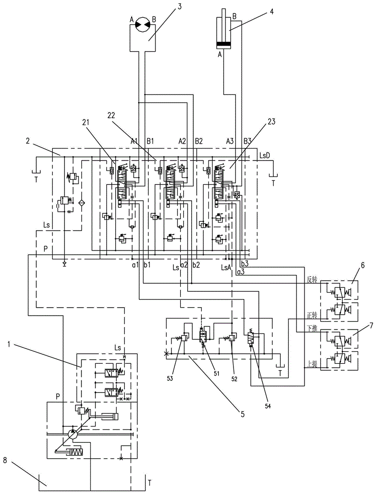
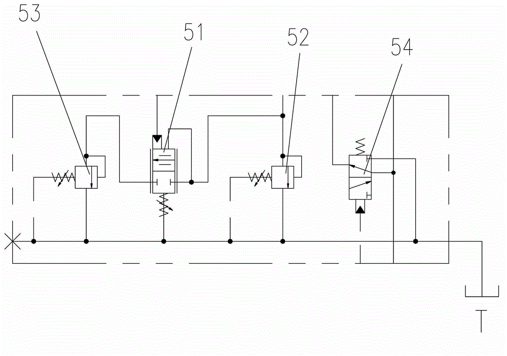
[0014] A single-pump hydraulic control circuit for the key rock drilling action of a cutting rig, which consists of a load-sensitive variable pump 1, a load-sensitive proportional multi-way valve 2, a rotary motor 3, a propulsion cylinder 4, and a hydraulic oil tank 8, etc. The main oil circuit: the logical control and pilot control oil circuit of the key rock drilling action of the cutting drilling rig is composed of the rock drilling logic control block 5, the rotary pilot handle 6, and the push pilot handle 7.

[0015] The function and configuration features of the load-sensitive proportional multi-way valve 2 are as follows: each valve has a pressure difference compensator and its load-sensitive external control port, and the pressure difference compensator of the propulsion-connected multi-way valve 23 especially has independent l...


PUM


Abstract

A single-pump hydraulic control loop of a key drilling action of a cutting drill rig comprises a load-sensitive variable pump, a load-sensitive multi-way valve, a rotary motor, a propulsion oil tank, a drilling logic control block, a rotation guide handle, a propulsion guide handle, and a hydraulic oil tank. An oil inlet of the load-sensitive variable pump is connected with the hydraulic oil tank. An oil outlet and a load-sensitive opening of the load-sensitive variable pump are connected with an oil inlet and a load-sensitive opening of the load-sensitive multi-way valve respectively. Each valve pressure difference compensator of the load-sensitive multi-way valve is provided with an external control opening. The external control openings are connected with the drilling logic control block. The rotation guide handle and the propulsion guide handle are connected with the drilling logic control block or a guide control opening of the load-sensitive multi-way valve. The double-pump hydraulic control loop has the advantages that power head rotation-proportion-controlled propulsion is achieved, high-speed rotating with propulsion prior to rotation is achieved, fast rod lifting while retaining certain rotation speed is achieved, and the like.

Description

Technical field [0001] The invention relates to a single-pump hydraulic control circuit for key rock drilling actions of a cutting drilling rig. Background technique [0002] The cutting drilling rig is a new type of rock drilling rig. Its operating mechanism is high-speed rotary crushing drilling. It has the outstanding advantages of high speed, high efficiency, simplicity and convenience for drilling operations in shale, sandstone and other rock formations. Comprehensive analysis of the current hydraulic systems of cutting drilling rigs of various brands , are all developed based on the simple improvement of the hydraulic system of small or medium excavators. Compared with the excavator, the cutting drilling rig subtracts the three actions of the swing arm, the breaker and the bucket, and increases the three actions of the power head propulsion, the power head rotation, and the air compressor. The breaker unit and the bucket unit realize the control of the three actions o...

Claims


Application Information

Patent Timeline
IPC IPC(8): E21B4/02E21B44/06F15B11/02F15B13/02
Inventor 王东升马海淮赵宏强林宏武
Owner SUNWARD INTELLIGENT EQUIP CO LTD
Why Eureka
Try Eureka