High-efficiency heat exchange fire grate of heat-conducting oil furnace

A technology of heat-conducting oil furnace and heat-exchanging furnace, which is applied to the grate, heat-storage heater and grate of hollow grate bars, can solve the problems of increased power of circulating pump motor, accelerated shedding speed, low heat-conducting efficiency, etc. The effect of reducing circulation resistance, cost, and power consumption

Active Publication Date: 2012-10-24
HEBEI GOLD BANGZI BOILER
View PDF4 Cites 2 Cited by
  • Summary
  • Abstract
  • Description
  • Claims
  • Application Information

AI Technical Summary

Problems solved by technology

If the traditional water-cooled grate structure is directly transplanted on the heat-conducting oil furnace to become an oil-cooled grate, it cannot meet the design requirements of the heat-conducting oil furnace
The main reason: the water-cooled grate is generally a parallel structure, and the diameter of the grate tube is generally between Φ51-Φ76mm, and has a certain inclination; when the flow rate of the heat transfer oil is determined, the flow rate of the heat transfer oil in the grate tube cannot be satisfied ( The higher the viscosity, the lower the flow rate)
In order to achieve the design flow rate, if the diameter of the grate tube is reduced, the rigidity of the grate tube will not be sufficient; if the wall of the grate tube is thickened, the heat conduction efficiency will be too low, and the outer tube wall is in an environment of high temperature and low conductivity. After the tube is oxidized, the shedding speed is accelerated, and it becomes a more fragile thin-walled tube
If the grate tubes are strengthened in series horizontally, the grate cannot be arranged in an inclined manner, and the circulation resistance of the heat transfer oil furnace is increased, which increases the power of the circulating pump motor. There is no self-circulation function in the furnace tube, and there is still unburned fuel on the oil-cooled grate, so even when the oil temperature drops to a low level, the circulating oil pump cannot be shut down, which increases the operating cost

Method used


Image

  • High-efficiency heat exchange fire grate of heat-conducting oil furnace
  • High-efficiency heat exchange fire grate of heat-conducting oil furnace
  • High-efficiency heat exchange fire grate of heat-conducting oil furnace

Examples


Embodiment Construction

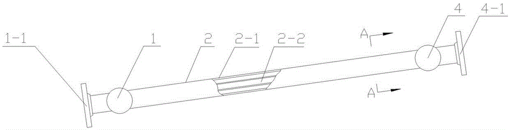
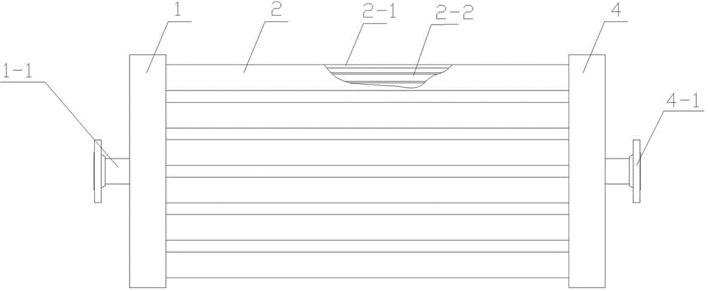
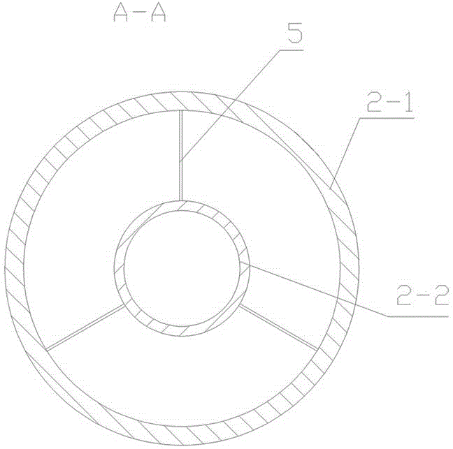
[0015] see Figure 1~Figure 3 , the present invention is used for fire grate for hand-fired coal-fired heat-conducting oil furnace, and its structure includes and connects the heat exchange tube 2 formed between the lower penetrating horizontal tube 1 and the upper penetrating horizontal tube 4 to form a grate shape, and the oil inlet 1- 1. The oil outlets 4-1 are respectively arranged on the lower through-through horizontal tube 1 and the upper through-through horizontal tube 4. The heat exchange tube 2 is a composite sleeve structure, and the inner sleeve 2-2 is a blind tube with one end closed. The terminal support 5 is positioned on the inner wall of the outer casing 2-1. This embodiment adds a blind pipe with one end closed on the basis of the existing heat exchange tube. Since the heat transfer oil in the blind pipe does not affect the circulation of the heat transfer oil in the outer casing 2-1, it is equivalent to reducing the liquid flow of the heat transfer oil. The...


PUM


Abstract

The invention discloses a high-efficiency heat exchange fire grate of a heat-conducting oil furnace, comprising a heat exchange tube in a structure, wherein the heat exchange is connected in parallel between a lower communicated horizontal tube and an upper communicated horizontal tube, and is formed like a fire grate; an oil inlet and an oil outlet are respectively arranged on the lower communicated horizontal tube and the upper communicated horizontal tube; the heat exchange tube is a compound sleeve tube structure; an internal sleeve tube is a blind tube which has a closed end and which is located on an inner wall of an external sleeve tube by means of an end bracket. The fire grate provided by the invention also ensures flow speed of heat-conducting oils in the tube under the condition that rigidity of the heat exchange tube is ensured so as to reach provisions of related state standards.

Description

technical field [0001] The invention relates to an improvement in the structure of a heat-conducting oil furnace, in particular to an improvement in the structure of a fire grate for a heat-conducting oil furnace when coal is used as an energy source. Background technique [0002] The heat-conducting oil furnace uses heat-conducting oil as the heat carrier, and through the forced circulation of the heat-oil pump, the hot oil is transported to the heat-consuming equipment through the pipeline, and then returned to the heat-conducting oil furnace for heating. It is a closed-circuit heating equipment that is currently preferred. Low-pressure high-temperature thermal energy conversion equipment. [0003] The main difference in the design requirements of heat transfer oil boilers and steam and hot water boilers is that: heat transfer oil furnaces require that the flow rate of heat transfer oil in the heat exchange tube is: the radiation section is not lower than 2m / s, and the...

Claims


Application Information

Patent Timeline
Patent Type & Authority Applications(China)
IPC IPC(8): F24H7/02F24H9/00F23H3/00
Inventor 陈社庭
Owner HEBEI GOLD BANGZI BOILER
Why Eureka
Try Eureka