Individual sighting telescope system

A sight and individual technology, which is applied in the field of optics and electronics, can solve the problems of deviation and inconsistency, and achieve the effects of convenient calibration, strong versatility, and fast shooting speed

Inactive Publication Date: 2012-10-24
蓝景恒
View PDF3 Cites 2 Cited by
  • Summary
  • Abstract
  • Description
  • Claims
  • Application Information

AI Technical Summary

Problems solved by technology

At this time, there is also the problem that there may be deviations when shooting with high precision at close range
[0005] In addition, shooting devices with different ballistics should use different scopes or calibrations, or even redesign and production

Method used


Image

  • Individual sighting telescope system
  • Individual sighting telescope system
  • Individual sighting telescope system

Examples


Embodiment Construction

[0028] The present invention will be further described below in conjunction with drawings and embodiments.

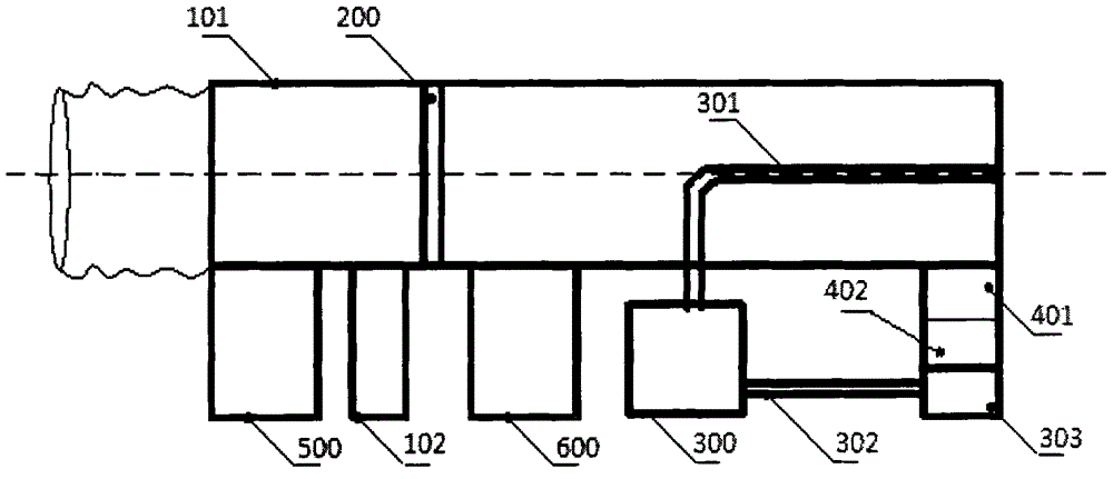
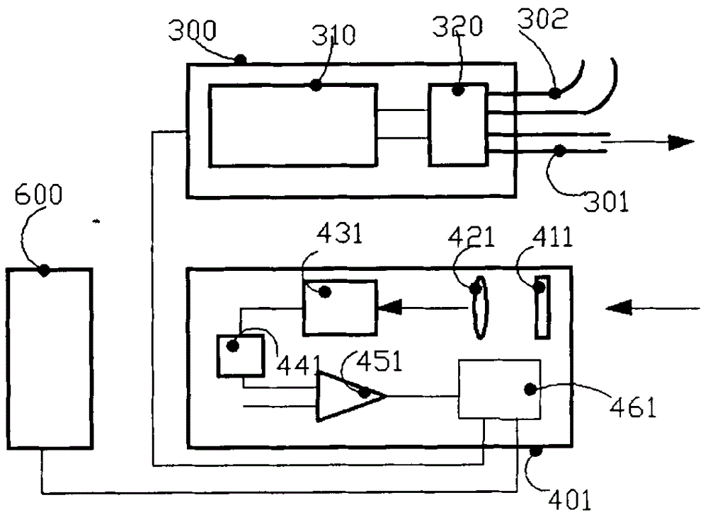
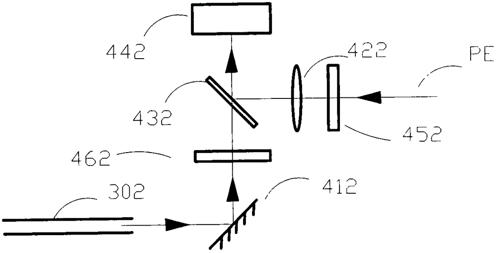
[0029] see figure 1 , the light emitted by the light source (300) can be coupled into the optical fiber (301, 302), the light transmitted by the optical fiber (301) is emitted along the central axis of the sight (101), and the reflected light reaching the target is received by the receiver (401), After passing through the circuit system (600), the target distance measurement is completed. The light of the optical fiber (302) enters the receiver (402) as a reference light, and the receiver (402) receives the light scattered by the particles in the air emitted by the optical fiber (301), and then the wind speed and wind direction are measured by the circuit system (600). The electronic level (500) outputs the angle signal to the circuit system (600). The circuit system (600) calculates according to the distance, wind speed and direction, angle and ballistic parameters, ...


PUM


Abstract

An individual sighting telescope system can be used for sniper rifles, machine cannons, bow and arrows and the like. Compared with the existing device, the individual sighting telescope system is easier to operate and regulate, can realize remote and super short-range precision shooting and can be used for sighting at night. Light of a light source (300) is coupled into optical fibers (301 and 302). Light of the optical fiber (301) exits along the central axis of a sighing telescope (101), reflected light toward a target is received by a receiver (401), and the measurement of a target distance is completed after the reflected light passes through a circuit system (600). Light of the optical fiber (302) enters a receiver (402), the receiver (402) receives the light scattered by overhead particles via the optical fiber (301), and the circuit system (600) is used for completing the wind speed and wind direction measurement. An electronic level device (500) inputs an angle signal into the circuit system (600). The circuit system (600) performs calculation according to the distance, wind speed and wind direction, angle and ballistic parameters, and inputs sighting points into a reticle (200) consisting of a transparent display screen.

Description

technical field [0001] The invention belongs to the fields of optics and electronics, and relates to a sight system, in particular to a high-precision sight system integrating target distance measurement, angle, wind speed and wind direction. It can be used for shooting devices such as sniper rifles, machine guns, bows and arrows. Background technique [0002] The scope is generally composed of a telescope optical system, and more often a Kepler telescope system. Its working principle is: the target is enlarged by the objective lens and imaged upside down on the reticle, then converted into an upright image by the image transfer system, and projected onto the eyepiece, so that the shooter can aim and shoot. Usually there is a problem with the adjustment mechanism of the up and down (distance) reticle and the left and right reticle of the scope. Some sights have left and right and up and down adjustment mechanisms on the reticle, while others are designed on the transfer le...

Claims


Application Information

Patent Timeline
Patent Type & Authority Applications(China)
IPC IPC(8): F41G1/36F41G1/467F41G1/473
Inventor 蓝景恒
Owner 蓝景恒
Why Eureka
Try Eureka