Electrochemiluminescence imaging system

A technology of electrochemiluminescence and luminescence imaging, which is applied in the direction of chemiluminescence/bioluminescence and analysis through chemical reactions of materials, etc. and luminous intensity dependence, to achieve the effect of low cost, high signal-to-noise ratio, and high sensitivity

A technology of electrochemiluminescence and luminescence imaging, which is applied in the direction of chemiluminescence/bioluminescence and analysis through chemical reactions of materials, etc. and luminous intensity dependence, to achieve the effect of low cost, high signal-to-noise ratio, and high sensitivity

CN102749323AActive Publication Date: 2012-10-24FUZHOU UNIV

Image

  • Electrochemiluminescence imaging system
  • Electrochemiluminescence imaging system

Examples


Embodiment Construction

[0009] The present invention will be further elaborated below in conjunction with the accompanying drawings and embodiments.

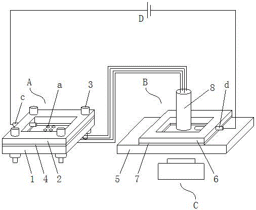
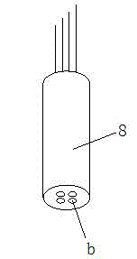
[0010] refer to Figure 1~2 , an electrochemiluminescence imaging system, comprising an electrochemical reaction cell A, an electrochemiluminescence imaging cell B, a regulated DC power supply C, and a CCD imaging unit D, the electrochemical reaction cell A communicates with at least one bipolar electrode The electrochemiluminescence imaging cell B is electrically connected, one pole of the bipolar electrode is arranged in the electrochemical reaction cell A for electrochemical reaction, and the other pole of the bipolar electrode is arranged in the electrochemiluminescence imaging cell B In order to carry out electrochemiluminescence reaction and imaging, the two poles of the bipolar electrode are connected by wires so that the electrochemical reaction cell A and the electrochemiluminescence imaging cell B only exchange electrons without exchanging su...


PUM

PropertyMeasurementUnit
diameteraaaaaaaaaa

Abstract

The invention relates to an electrochemiluminescence imaging system, which comprises an electrochemical reaction pool, an electrochemiluminescence imaging pool, a stabilized voltage direct current power supply and a CCD (Charge Coupled Device) imaging unit, wherein the electrochemical reaction pool is electrically connected with the electrochemiluminescence imaging pool through at least one bipolar electrode; a pole of the bipolar electrode is arranged in the electrochemical reaction pool, the other pole of the bipolar electrode is arranged in the electrochemiluminescence imaging pool, and the two poles are connected through a wire; a driving electrode is also arranged in the electrochemical reaction pool and the electrochemiluminescence imaging pool respectively; the two driving electrodes are connected with a positive electrode and a negative electrode of the stabilized voltage direct current power supply through a wire respectively; and an electrochemiluminescence phenomenon in the electrochemiluminescence imaging pool is recorded by the CCD imaging unit. The electrochemiluminescence imaging system has the advantages of simple instrument, low cost, high detection sensitivity, quickness and high energy, and has great significance to promotion of development of basic electrochemical science research, high-flux and high-sensitivity analysis detection and a screening technology of electro-catalysts in fuel cells.

Description

technical field [0001] The invention relates to an electrochemiluminescence imaging system, which is especially suitable for electrochemical analysis and electrocatalyst screening in fuel cells. Background technique [0002] The electrochemiluminescence imaging method can observe the distribution of the electrochemiluminescence intensity on the electrode surface very well, and the electrochemiluminescence intensity has a great dependence on the activity of the electrode surface, so the electrochemiluminescence imaging method can be used to visualize , Visually see the electroactive area on the electrode surface and the distribution state of the active material on the electrode surface, which provides convenience for the microscopic study of the electrochemiluminescence reaction process and detection. At present, there is an electrochemiluminescence imaging technology that uses long bipolar electrodes in the same electrolytic cell to experiment with the conversion of current ...

Claims


Application Information

Patent Timeline
24 Oct 2012
Publication
CN102749323A
IPC
G01N21/76
Inventors
池毓务; 林小梅