Power converting apparatus and capacitor cover thereof

A technology for power conversion devices and capacitors, applied in the direction of capacitors, tubular capacitors, power electronics modification, etc., can solve problems such as the inability to discharge the air inside the cover, and the inability to insert capacitors smoothly, and achieve the effect of maintaining cooling efficiency

Active Publication Date: 2012-10-24
YASKAWA DENKI KK
View PDF9 Cites 7 Cited by
  • Summary
  • Abstract
  • Description
  • Claims
  • Application Information

AI Technical Summary

Problems solved by technology

However, at this time, since there is no gap between the capacitor and the capacitor cover, the air inside the cover cannot be exhau

Method used


Image

  • Power converting apparatus and capacitor cover thereof
  • Power converting apparatus and capacitor cover thereof
  • Power converting apparatus and capacitor cover thereof

Examples


Embodiment Construction

[0018] Hereinafter, one embodiment will be described with reference to the drawings.

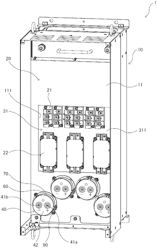
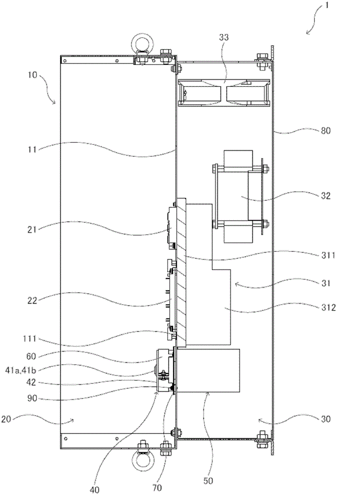
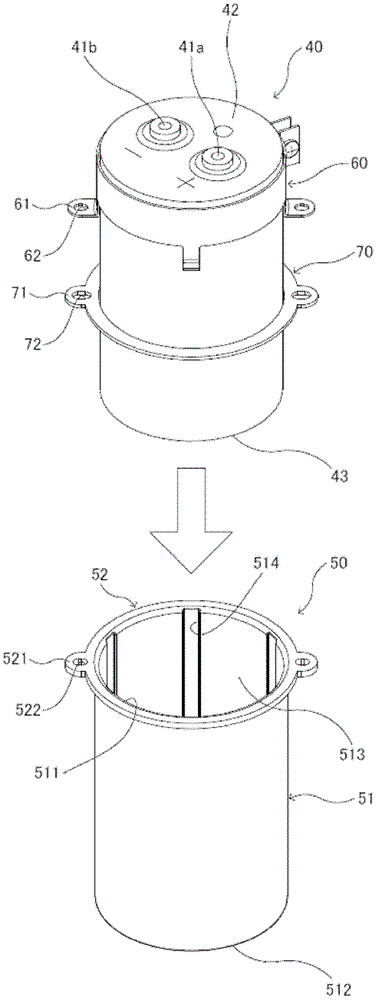
[0019] Such as figure 1 and figure 2 As shown, the power conversion device 1 of the present embodiment is an inverter device that converts DC power to AC power. This power conversion device 1 has: a frame 10 provided with a frame base 11; a main body 20 disposed on the front side (one side, figure 1 The left side and the front side of the paper, figure 2 the left side in); the wind tunnel part 30 is disposed on the rear side of the frame base 11 (the other side, figure 1 In the right side of the paper, into the deep side, figure 2 The right side of the middle), so that the cooling air flows; such as cylindrical capacitors 40 such as aluminum electrolytic capacitors; bottomed cylindrical capacitor cover 50; ring-shaped capacitor clip 60 (fixed member); ring-shaped metal plate 70 ; a body cover (not shown) covering the body portion 20 ; and a wind tunnel cover 80 covering the wind tunn...


PUM


Abstract

The invention can be used to keep the cooling efficiency of the capacitor and enable the capacitor to insert in the capacitor cover successfully. A power converting apparatus (1) includes a housing(10), a cylindrical capacitor(40), and a cylindrical capacitor cover(50). The housing includes a housing base(11), a main body(20), and an air duct(30). The air duct(30) is disposed on a second surface of the housing base. The capacitor(40) penetrates through the housing base so that a part of the capacitor (40)is disposed in the main body(20) while a rest part of the capacitor is disposed in the air duct. The capacitor cover(50) is disposed on the housing base(11) and covers the rest part of the capacitor(40). The capacitor cover (50) includes an elastic material and an inner surface. The capacitor cover (50) includes a groove(514) having the same size of the inner diameter of the inner peripheral surface (513) disposed on the inner surface in an axial direction of the capacitor cover.

Description

technical field [0001] The disclosed embodiments relate to a power conversion device and a capacitor cover thereof, which perform conversion from DC power to AC power or from AC power to DC power. Background technique [0002] Generally, a power conversion device has a cylindrical capacitor with a large electrostatic capacity. In order to realize the miniaturization of the power conversion device and improve the cooling efficiency of the capacitor, the capacitor generally adopts the following structure. At this time, a capacitor cover is provided for waterproofing and dustproofing the part where the capacitor is arranged in the wind tunnel. [0003] For example, Patent Document 1 discloses a capacitor cover (jig) for attaching a cylindrical capacitor (aluminum electrolytic capacitor) to a housing base (body base). The capacitor cover is made of a material such as a plastic material having a predetermined elasticity with a predetermined hardness, and is made into a bottomed...

Claims


Application Information

Patent Timeline
IPC IPC(8): H02M7/00H01G2/10
CPCH01G4/28H01G4/224H05K7/20918H01G2/10
Inventor 永野纯明岸本一孝古城眞人
Owner YASKAWA DENKI KK
Why Eureka
Try Eureka