Microfluidic chip applicable to research on cell migration

A microfluidic chip and cell migration technology, which can be used in special-purpose bioreactors/fermenters, microbial measurement/inspection, enzymology/microbiology devices, etc., and can solve problems such as difficult automatic operation and cell damage

Inactive Publication Date: 2012-10-31
PEKING UNIV
View PDF0 Cites 2 Cited by
  • Summary
  • Abstract
  • Description
  • Claims
  • Application Information

AI Technical Summary

Problems solved by technology

[0003] The purpose of the present invention is to solve the problems in the prior art, such as unavoidable damage to cells, difficulty in automatic operation and quantitative measure...

Method used


Image

  • Microfluidic chip applicable to research on cell migration
  • Microfluidic chip applicable to research on cell migration
  • Microfluidic chip applicable to research on cell migration

Examples


preparation example Construction

[0031] The following examples illustrate the preparation method of microfluidic chips. In the following examples, relatively simple photoresist SU-8, AZP 4620 and PDMS are used to prepare, but it does not mean that microfluidic chips can only be prepared by such methods. Those skilled in the art It can be understood that any existing technology in the art can be used to prepare the microfluidic chip with the structure of the present invention.

[0032] We first used photolithography to fabricate templates for the microfluidic channel and the control channel, respectively. The control channel was made with negative glue SU8-2010. Pour negative glue SU8-2010 onto a clean silicon wafer, rotate at 1000rpm for 1 minute, bake on a heating plate at 65°C for 5 minutes, bake on a heating plate at 95°C for 10 minutes, expose, repeat baking at 65°C for 5 minutes, Bake on a heating plate at 95°C for ten minutes, develop, and heat on a heating plate at 150°C for 3 hours to reinforce the g...

Embodiment 1

[0054] Structure of the microfluidic chip. This embodiment describes in detail a preferred structure of the microfluidic chip of the present invention, the structure is as figure 1 shown. The fluid delivery channel connected to the inlet is bifurcated to form 4 new fluid delivery channels, and each new fluid delivery channel is bifurcated to form 2 new fluid delivery channels, and the final 8 fluid delivery channels are widened to form cell growth microfluidic channel. The control layer includes a total of 2 control channels, of which the red control channel entrance is on the right, and the control channel directly connected to the entrance is bifurcated to form 4 new control channels, and each new control channel is formed above the cell growth microfluidic channel There are 8 cavities, so this control channel corresponds to controlling 4 cell growth microfluidic channels (corresponding to the 1st, 3rd, 5th, and 7th from bottom to top). Similarly, the green control channe...

Embodiment 2

[0056] Effect of different blank area areas on cell migration speed.

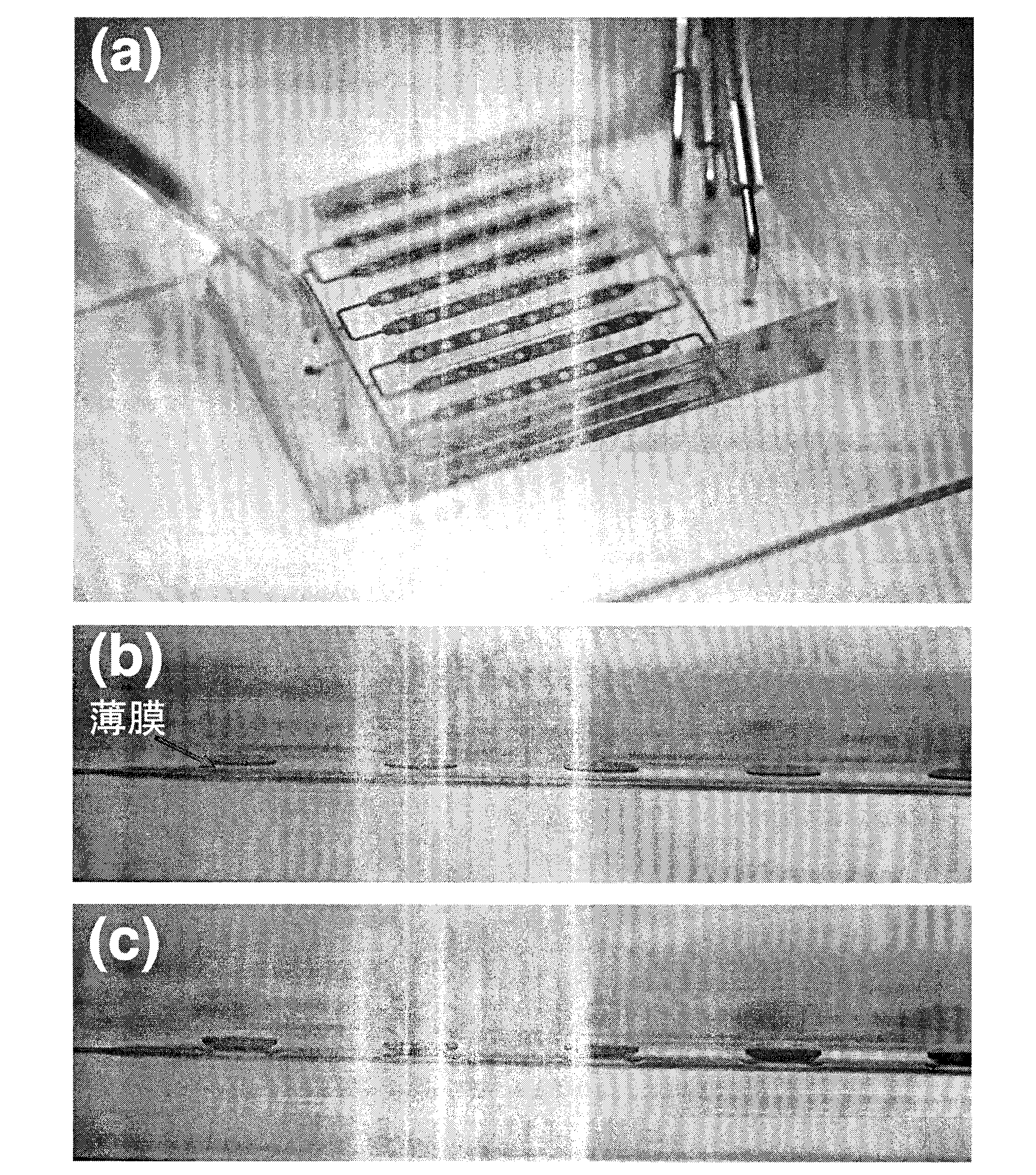
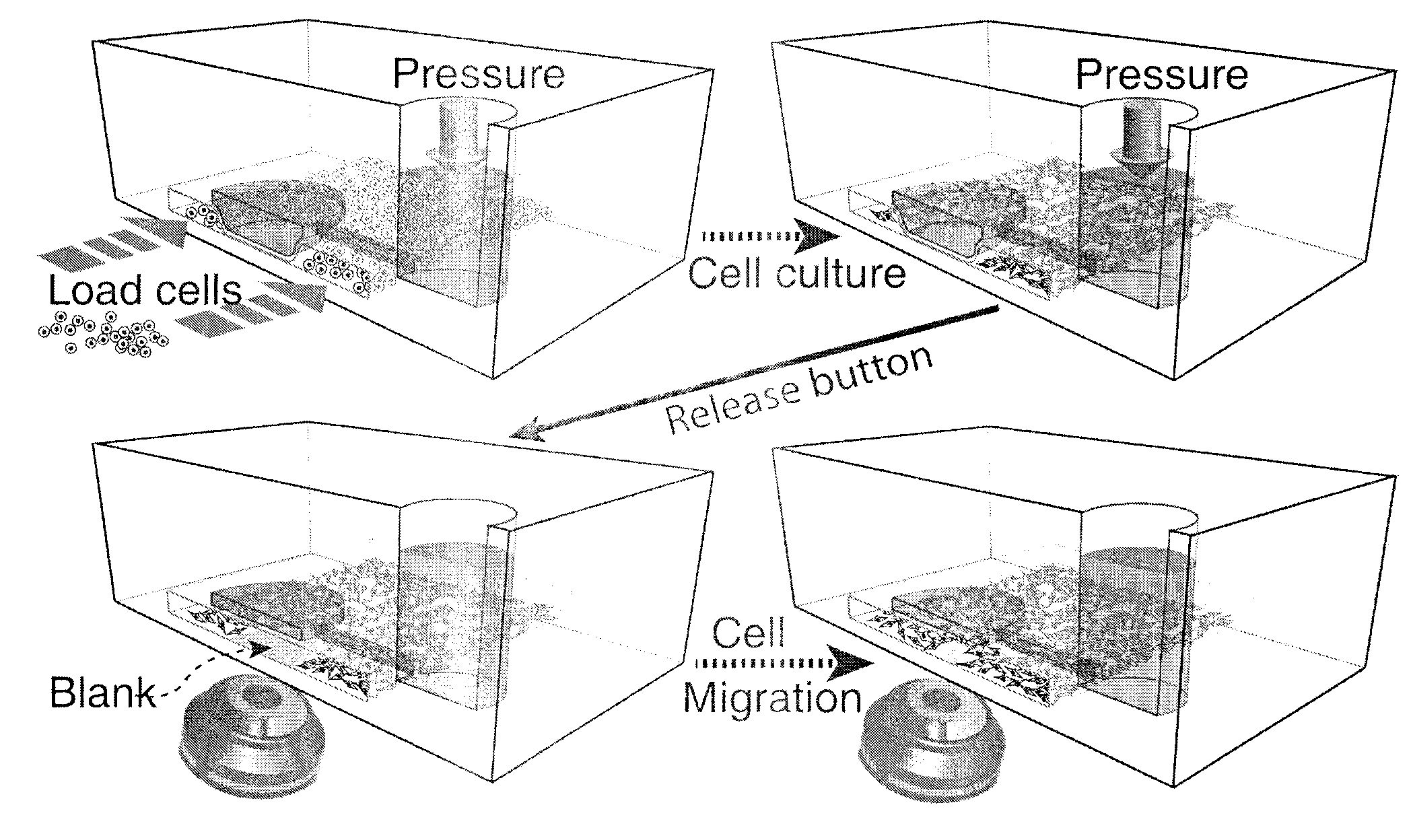
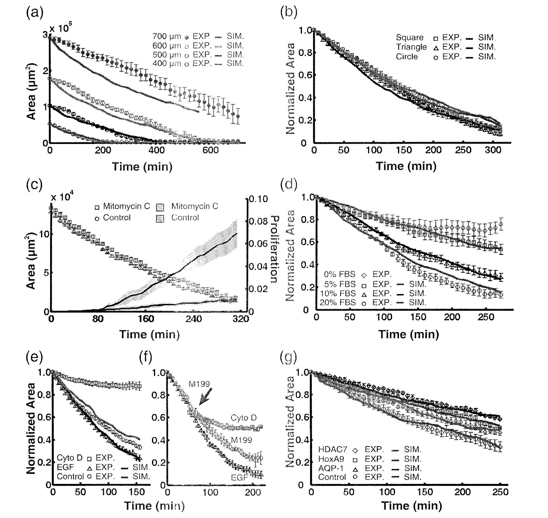
[0057] We designed the button valve (that is, the cavity and the connection layer at the cavity) into circles with diameters of 700 microns, 600 microns, 500 microns, and 400 microns in turn, which are used for microfluidic channels for culturing cells (that is, cell growth microfluidics). track) with a width of 1000 μm. The size of the blank "scar" area (that is, the area of ​​the blank area) at each moment is obtained by image processing methods, and a graph of the number of pixels in the area and time is drawn. We find that the four curves corresponding to different diameters are almost parallel to each other, because the slope indicates that the cells The size of the migration speed, thus, we deduce that the cell migration speed has nothing to do with the initial "scar" area ( image 3 a).


PUM


Abstract

The invention relates to a microfluidic chip applicable to research on cell migration. The microfluidic chip comprises a microfluidic layer, a control layer and a connecting layer, wherein the connecting layer is used for connecting the microfluidic layer and the control layer; the microfluidic layer is provided with at least one microfluidic channel; the inner surface of the microfluidic channel consists of a material suitable for growth of cells; the control layer is provided with at least one control channel; the cell growth microfluidic channel and the at least one control channel is provided with at least one intersected point; the connecting layer at the position of the intersected point consists of an elastomer material; when pressure in the control channel is increased to a certain value, the elastomer connecting layer at the position of the intersected point is expanded towards the direction of the microfluidic layer and is contacted with the inner surface of the microfluidic channel to form a contact surface with certain size; and the width of the contact surface is less than that of the microfluidic channel at the position of the intersected point, so that the microfluidic channel is in the communication state. The microfluidic channel is simple to prepare and convenient to use and does not damage to the cells in the process of researching on the cell migration.

Description

technical field [0001] The invention relates to a microfluidic chip, in particular to a cheap, easy-to-prepare microfluidic chip suitable for large-scale high-throughput cell migration tests. Background technique [0002] Cell migration is very important to many biological processes, and further understanding of its detailed mechanism can bring more applications to biological sciences. The streaking method is the most common method used to study cell migration in biological experiments, but the process of generating scars by the streaking method will cause great damage to the cells, which is difficult to avoid by the streaking method, and the traditional streaking method Due to its difficulty in automatic operation and quantitative measurement, the line method limits its application in large-scale high-throughput experiments. Many experimental groups have developed mechanisms to study wound healing in microfluidic chips, using methods such as electrical signals, trypsinizat...

Claims


Application Information

Patent Timeline
IPC IPC(8): C12M1/00C12Q1/02
Inventor 黄岩谊庞玉宏郑春红虞之龙周莹周宏伟
Owner PEKING UNIV
Why Eureka
Try Eureka