ZigBee-based wireless dynamometer

A dynamometer and wireless technology, applied in the field of wireless dynamometer, can solve problems such as inconvenient real-time detection and wireless transmission, cumbersome installation, limited data storage capacity, etc., to achieve easy analysis of small problems, safe and reliable data transmission, network The effect of high quality and low price service

Inactive Publication Date: 2012-10-31
南京南大数字科技有限责任公司
View PDF3 Cites 10 Cited by
  • Summary
  • Abstract
  • Description
  • Claims
  • Application Information

AI Technical Summary

Problems solved by technology

The displacement sensor in the primary instrument adopts the method of pulling wires, which is not convenient for real-time detection and wireless transmission, and the measurement accuracy cannot be guaranteed, which is prone to failure. Moreover, cables are used to transmit data between the primary instrument and the secondary instrument, and the power supply adopts the way of charging power supply , the whole instrument is not only large in size, many parts, cumbersome to install, but also has limited data storage capacity.
The data required for the production work map needs to be connected to a variety of sensors, and the oil well production can only be measured after the data is processed, which leads to intricate and cumbersome field wiring, and the production measurement process is time-consuming and inefficient
Moreover, some dynamometer products use GPRS network and CDMA network, and the construction cost is very high, which is not suitable for ordinary oil fields.

Method used


Image

  • ZigBee-based wireless dynamometer
  • ZigBee-based wireless dynamometer

Examples


Embodiment Construction

[0017] In order to better understand the technical content of the present invention, specific embodiments are given together with the attached drawings for description as follows.

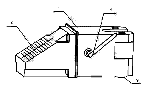
[0018] Also refer to figure 1 and figure 2 . First of all, from the appearance, the U-shaped solar wireless dynamometer of the present invention consists of a box body 1, a solar panel 2 fixed on the front side of the box body, a load sensor 3 fixed below the U-shaped bayonet of the box body, and a transmitter fixed on one side of the box body 1. The antenna is connected to the circuit in the box body 1 to form a structure.

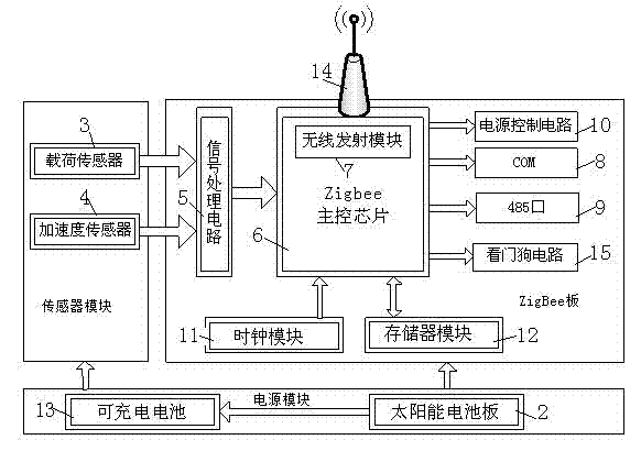
[0019] Now mainly introduce the internal principle of the wireless dynamometer. The ZigBee-based wireless dynamometer includes: power module, sensor module and ZigBee board. The power module is used to provide working voltage to the ZigBee board sensor module and ZigBee board. board, and output at least one sensor signal to the ZigBee board, the ZigBee board processes the ...


PUM


Abstract

The invention relates to a ZigBee-based wireless dynamometer, which comprises a sensor module, a power supply module and a ZigBee panel and is mainly characterized in that a ZigBee wireless network transmission mode is provided, the working condition of an oil pumping well can be monitored remotely in real time, and the well yield is estimated. According to the invention, a solar panel is designed for supplying power to a chargeable manner, and a battery does not need to be replaced frequently. The ZigBee-based wireless dynamometer disclosed by the invention can store a large amount of dynamometer diagrams, read historical data or carry out real-time measurement in a wireless manner and obtain a measuring result with high precision and high stability on an oil pumping well.

Description

technical field [0001] The invention relates to a measuring device for a well power diagram of a pumping unit in an oil field, in particular to a ZigBee-based wireless dynamometer used in an oil field automation system. Background technique [0002] In oilfields with mechanical oil production, the oil well indicator diagram provides an important means for oil production engineers to analyze the working status of downhole pumps and pumping units. It is of great significance and is a key indicator for analyzing and diagnosing whether the pumping well is normal. The production status of the oil well is very complicated, and there are many factors affecting the downhole operation of the oil pump, so it is very difficult to directly measure the work diagram of the downhole oil pump. If you want to know the working condition of the pump in the well, you can only use the dynamometer to measure the power diagram of the polished rod on the ground for analysis and diagnosis. At pres...

Claims


Application Information

Patent Timeline
Patent Type & Authority Applications(China)
IPC IPC(8): E21B47/009E21B47/12E21B47/26
Inventor 李训铭黄春海荆志军李翰涛
Owner 南京南大数字科技有限责任公司
Why Eureka
Try Eureka