Self-excitation oscillating-flow heat pipe with netted pipeline

A technology of self-excited oscillation and mesh pipes, which is applied in the field of heat pipes, can solve problems such as pipe blockage and low start-up temperature, and achieve the effects of solving pipe blockage, improving performance, and simple manufacturing process

Active Publication Date: 2012-10-31
FOSHAN KAICHANG LIGHTING ELECTRICAL APPLIANCE
View PDF4 Cites 3 Cited by
  • Summary
  • Abstract
  • Description
  • Claims
  • Application Information

AI Technical Summary

Problems solved by technology

[0003] The purpose of the present invention is to provide a self-excited oscillating flow heat pipe with mesh pipes, which well solves the problem of pipe blockage and has a lower start-up temperature

Method used


Image

  • Self-excitation oscillating-flow heat pipe with netted pipeline
  • Self-excitation oscillating-flow heat pipe with netted pipeline
  • Self-excitation oscillating-flow heat pipe with netted pipeline

Examples


Embodiment 1

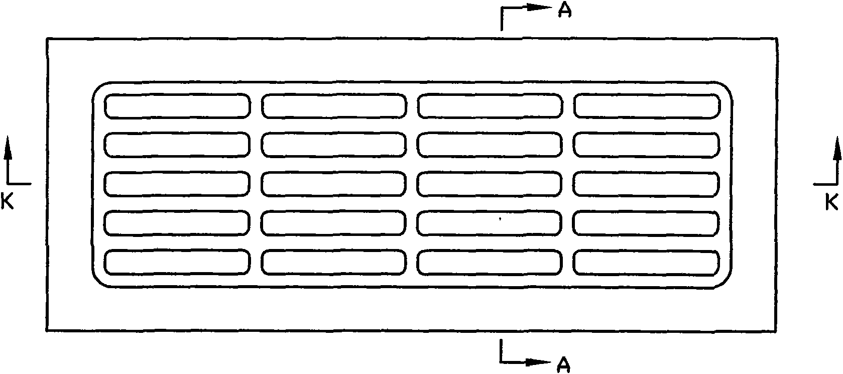
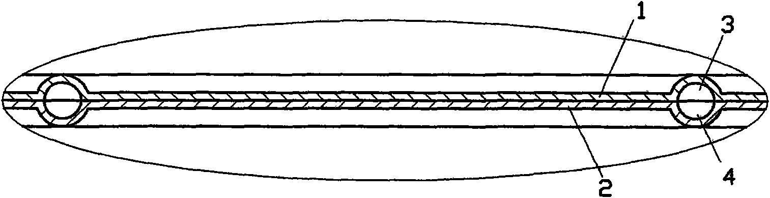
[0034] see Figure 1 to Figure 5 , a self-excited oscillating flow heat pipe with mesh pipes, which is composed of two layers of metal plates 1 and 2, and the two layers of metal plates are integrally formed with grooves 3 and 4, and the grooves 3 and 4 are formed on the two layers of metal plates The spliced ​​surfaces of the self-excited oscillating flow heat pipe form the pipeline for sealing the working fluid. or as Image 6 , Figure 7 As shown, only one layer of metal plate 1 is integrally formed with a groove 3, while the other layer of metal plate 2 has no groove. In the pipeline formed by the grooves 3, 4 (or only the groove 3), the working medium (not shown in the figure) forms a plunger between the liquid phase and the gas phase. The working medium can be water, ethanol, R142b, R123, etc. The two-layer metal plates 1, 2 can be assembled by means of welding, bonding and the like.

[0035] Such as figure 1 As shown, viewed from the direction perpendicular to the...

Embodiment 2

[0037] see Figure 8 to Figure 12 The difference between this embodiment and Embodiment 1 is that the depth of the grooves 3, 4 on the two-layer metal plates 1, 2 is smaller than the thickness of the metal plates where they are located, thus making the two-layer metal plates 1, 2 The side facing the outside can be made into a flat surface, which is more likely to be in close contact with the surface of the object that needs heat transfer.

[0038] Another groove structure of this embodiment can also be as Figure 13 , Figure 14 As shown, only one layer of metal plate 1 is integrally formed with a groove 3, while the other layer of metal plate 2 has no groove.

Embodiment 3

[0040] see Figure 15 , Figure 16 , Figure 17 and Figure 19 , the self-excited oscillating flow heat pipe with mesh pipes is made up of two layers of metal plates, one of which is formed by butt joints of bendable flexible metal plates 5 and non-bendable rigid metal plates 6a, 6b, and the flexible metal plates 5 is connected between two rigid metal plates 6a, 6b, and the other layer of metal plate is formed by the butt joint of bendable flexible metal plate 7 and non-bendable rigid metal plates 8a, 8b, flexible metal plate 7 is connected between two rigid Between the metal plates 8a, 8b. Seen from the cross-section of the metal plates, two layers of rigid metal plates 6a, 8a correspond to splicing, and two layers of flexible metal plates 5, 7 correspond to splicing. The part formed by the two layers of flexible metal plates 5 and 7 can be bent, which makes the self-excited oscillating flow heat pipe easier to bend and has better installation flexibility. The rigid meta...


PUM


Abstract

A self-excitation oscillating-flow heat pipe with a netted pipeline is spliced by two metal plates. Grooves are formed on at least one metal plate integrally, form a pipeline for sealing up working media on the spliced plane of the two metal plates, and have a crisscross grid structure when being viewed from a direction perpendicular to the planes of the metal plates. With the self-excitation oscillating-flow heat pipe with the pipe network, blockage of the pipeline is overcome well. The self-excitation oscillating-flow heat pipe with the netted pipeline has the advantages of good temperature-equalizing performance, quick heat-transfer, quick returning of working liquid media and the like. What's more, the starting temperature of the self-excitation oscillating-flow heat pipe is reduced, and heat transfer performance thereof is improved remarkably.

Description

technical field [0001] The invention relates to heat pipe technology, in particular to a self-excited oscillating flow heat pipe. Background technique [0002] Self-excited oscillating flow heat pipes all have a pipeline encapsulating working fluid, and the working fluid forms a plunger between liquid and gas phases in the pipeline. The existing self-excited oscillating flow heat pipes all adopt a single pipe structure, and the whole heat pipe has only one end-to-end connected pipe, which is prone to the problem of impurity blockage, which will increase the vapor pressure of the working medium in the pipe, and the circulation of the working medium is not smooth, and even cause pipe rupture. In addition, the single pipe structure also makes the starting temperature of the self-excited oscillating flow heat pipe higher, that is, the minimum temperature required for the self-excited circulation of the working medium in the pipe is higher, thereby reducing the heat conduction o...

Claims


Application Information

Patent Timeline
Patent Type & Authority Applications(China)
IPC IPC(8): F28D15/02F28F21/08
Inventor 吴育林
Owner FOSHAN KAICHANG LIGHTING ELECTRICAL APPLIANCE
Why Eureka
Try Eureka