Leak detector of vacuum system

A vacuum system and leak detection technology, which is applied in the direction of using liquid/vacuum to measure liquid tightness and detecting the appearance of fluid at the leakage point, can solve problems such as offset and affect the normal operation of the unit, and ensure personal safety , reduce loss and save cost

Inactive Publication Date: 2012-10-31
DONGGUAN NINE DRAGONS PAPER IND
View PDF10 Cites 1 Cited by
  • Summary
  • Abstract
  • Description
  • Claims
  • Application Information

AI Technical Summary

Problems solved by technology

[0003] Chinese patent document CN101876581A discloses a leak point finding method for copper tube leakage of power plant condenser, which is mainly used in the leak detection of copper tube. Content, electrical conductivity, hardness and other indicators to determine which side the leakage occurs. After investigating the leakage side, open the small doors at both ends of the half side, drain the water, and wrap the copper tube with plastic wrap on the side of the condenser. The nozzle is sealed, and the other side is checked with a candle flame one by one, because the leaked tube will have a vacuum leak, and without the interference of external wind, the flame will reach the leaked copper tube and will obviously go inward. offset
This method also needs to stop the unit and perform other operations to a certain extent before leak detection, which will still affect the normal operation of the unit, and the time-consuming problem still cannot be effectively solved

Method used


Image

  • Leak detector of vacuum system
  • Leak detector of vacuum system
  • Leak detector of vacuum system

Examples


Embodiment 1

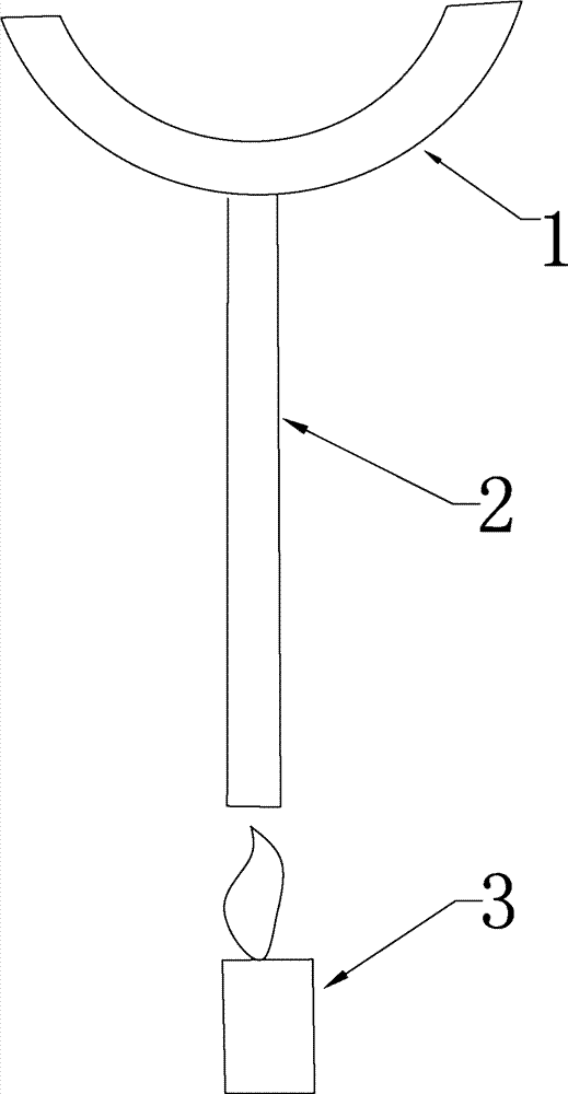
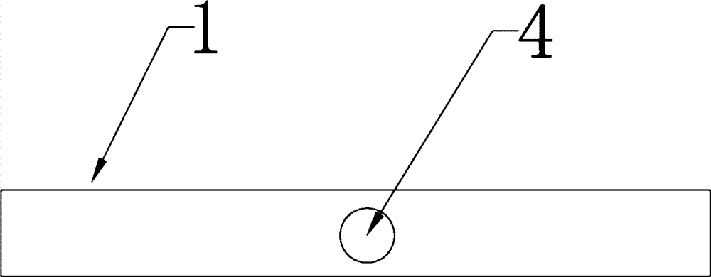
[0024] The vacuum system leak detector includes a detection part 1, a connection part 2 and an induction device 3, the connection part 2 is provided with a hollow tube, the detection part 1 is provided with a detection hole 4, and one end of the hollow tube is connected to the The detection hole 4 of the detection part 1 is connected, an air flow channel is formed between the detection hole 4 and the hollow tube, and the sensing device 3 is placed at the other end of the hollow tube. Especially for some spaces where the unit has high temperature and pipelines are densely covered, and the staff cannot approach the flange to check for leaks, the invention can be used for effective and convenient inspection. The detection part 1 is moved along the pipeline or the flange. When moving When reaching the leaking place, according to the principle of high and low pressure air flow, the detection hole 4 communicates with the hollow tube of the connecting part 2, and the air flow passes t...

Embodiment 2

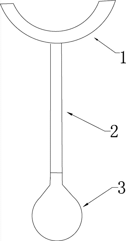
[0032] The difference between this embodiment and the first embodiment is that the connection part 2 is a telescopic tube. The connecting part 2 can be expanded and contracted, and the length of the connecting part 2 can be adjusted arbitrarily during detection, so as to adapt to the detection of pipes and flanges in different places.

[0033] The induction device 3 is a balloon, and the balloon is sheathed at the end of the hollow tube. In the power plant, there will be a large flammable hidden danger, so it is necessary to control the open flame. The sensing device 3 of the present embodiment is a balloon, and the balloon is an inflated soft leather balloon, which is spherical in normal state. When the air pressure is lower than the outside air pressure, the balloon will automatically inhale and deform. When testing, put the balloon on the end of the hollow tube at the connection part 2, and then approach the pipe or flange to be tested. When a leak is detected, the balloo...


PUM


Abstract

The invention belongs to the technical field of leak detection for pipelines of vacuum systems and particularly relates to a leak detector of a vacuum system. The leak detector comprises a detection part, a connection part and a sensing device, wherein the connecting part is provided with a hollow pipe, the detection part is provided with a detection hole, one end of the hollow pipe is connected with the detection hole of the detection part, an air runner is formed between the detection hole and the hollow pipe, and the sensing device is arranged at the other end of the hollow pipe. When the leak detector is used, a unit is unnecessary to decelerate and stop and can be used under a normal operation state, not only is time consumption prevented, but also losses caused by continuous top can be reduced, the cost can be saved, furthermore, the personal safety of workers can be guaranteed and leaks can be rapidly detected and handled as soon as possible.

Description

technical field [0001] The invention belongs to the technical field of vacuum system pipeline leak detection, in particular to a vacuum system leak detector. Background technique [0002] The vacuum system of the power plant is mainly a water ring mechanical vacuum pump, which establishes a certain vacuum in the cylinder and condenser during startup and continuously removes non-condensable gas in the vacuum system of the steam turbine during normal operation to maintain the vacuum of the condenser. Most of the vacuum leakage of the electric condenser occurs at the copper pipe and the flange. The copper pipe will burst or perforate due to long-term use and leak, while the flange will be leaked due to the insufficient tightness of the screw or the sealing ring. The leakage of the vacuum system will cause the machine to idle or the vacuum load to be insufficient, which will affect the normal operation. When the copper pipe flange of the electric condenser leaks, the traditiona...

Claims


Application Information

Patent Timeline
Patent Type & Authority Applications(China)
IPC IPC(8): G01M3/04
Inventor 张跃松刘灼星刘祥星林新阳张成飞
Owner DONGGUAN NINE DRAGONS PAPER IND
Why Eureka
Try Eureka