DSRC (dedicated short range communication)-based vehicle positioning device, method and DSRC application system
A technology for vehicle positioning and positioning antennas, applied in instruments, ticketing equipment, etc., can solve problems such as positioning errors, low positioning accuracy, and large fluctuations in microwave signal field strength, achieving accurate real-time monitoring or management, high precision, and solving problems. The effect of following interference
- Summary
- Abstract
- Description
- Claims
- Application Information
AI Technical Summary
Problems solved by technology
Method used
Image
Examples
Embodiment 1
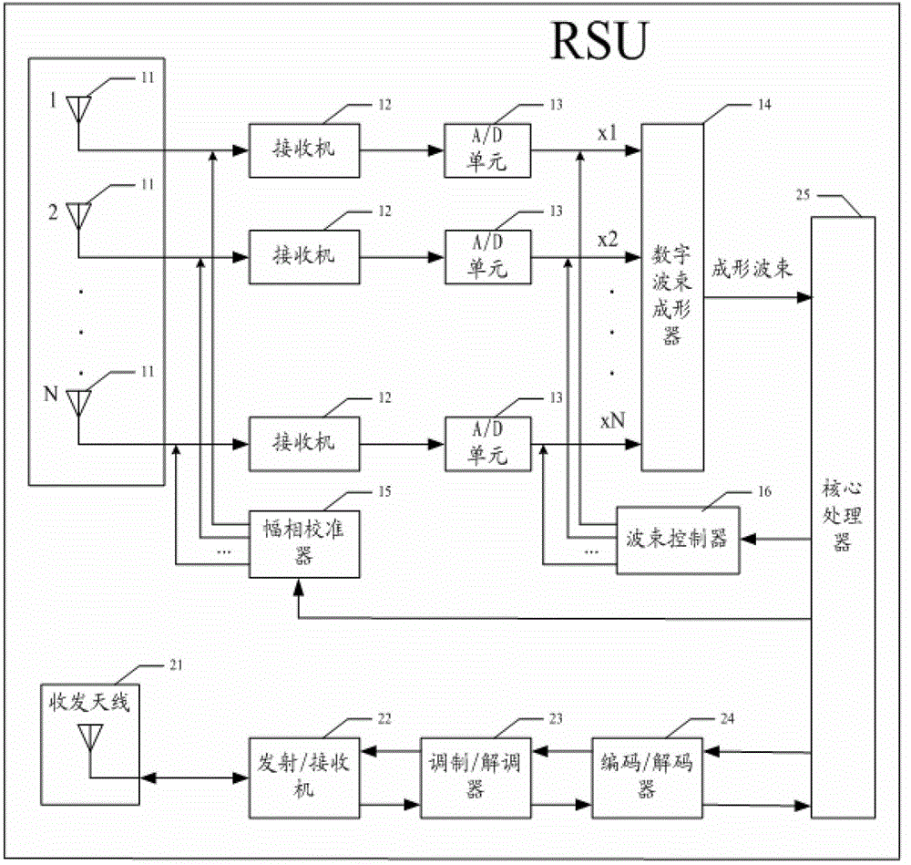
[0032] The vehicle positioning method of the present application is based on the information interaction between the RSU and the OBU. Among them, the RSU includes an outdoor unit and an indoor unit. The RSU outdoor unit has a transceiver antenna for sending microwave signals to the OBU and receiving microwave signals from the OBU. The RSU outdoor unit is usually installed above the road or on the side of the road. The RSU indoor unit is used for Control the RSU outdoor unit and process the information received and sent by the RSU outdoor unit; the OBU also has an antenna for sending microwave signals to the RSU and receiving microwave signals from the RSU. The OBU is usually installed in the vehicle, such as fixed on the vehicle on the front windshield.
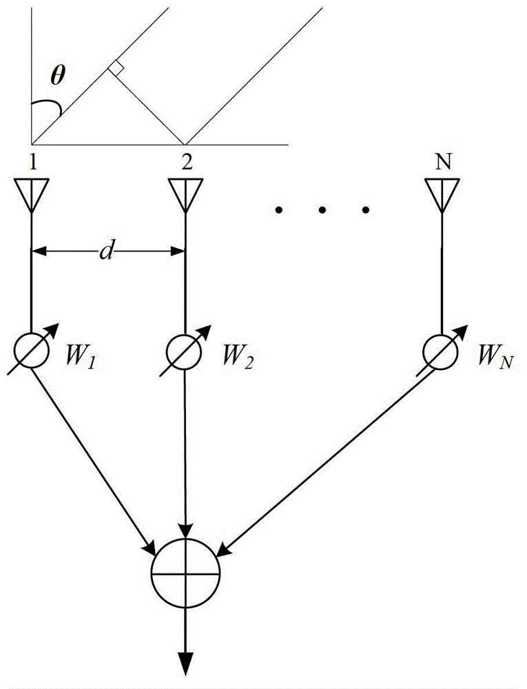
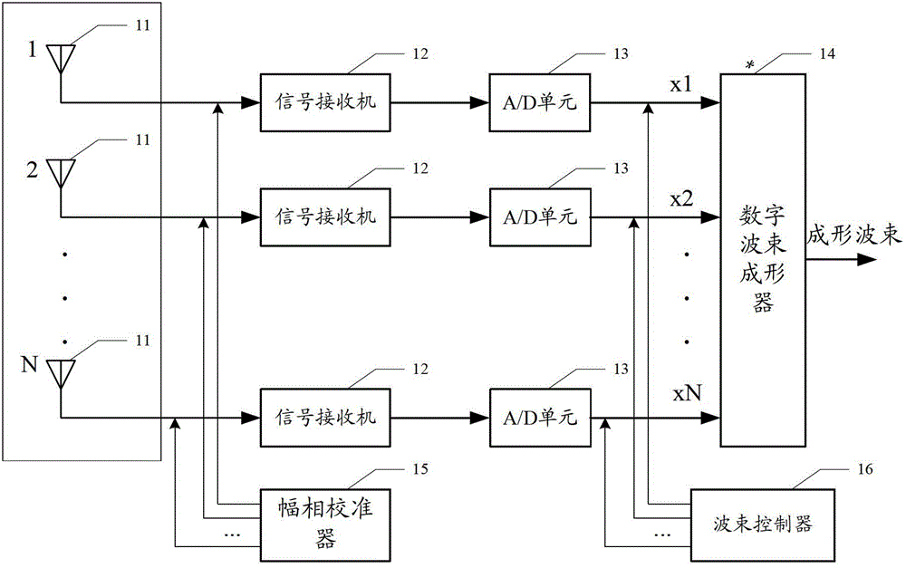
[0033] Please refer to figure 1 or figure 2 , this embodiment discloses a vehicle positioning device, the vehicle positioning device is set in the RSU of the ETC system, mainly including:
[0034] Positioning antenna, the...
Embodiment 2
[0063] The difference from the first embodiment is that the positioning device of the first embodiment has a set of positioning antennas for one-dimensional positioning of the microwave signal from the OBU, for example, using a set of positioning along the road extension direction (longitudinal) For the antenna, the angle between the microwave signal and the normal line of the antenna array is obtained through Embodiment 1 and then used as the pitch angle of the OBU to calculate the longitudinal position coordinates of the coverage area of the OBU in front of the vertical projection point of the RSU antenna. However, the positioning antennas of this embodiment have two groups, and the arrangement directions of the receiving antennas in the two groups of positioning antennas are perpendicular to each other. In addition to obtaining the longitudinal position coordinates of the OBU, a group of positioning antennas perpendicular to the road extension direction (horizontal directio...
Embodiment 3
[0065] Please refer to Figure 4 , the present embodiment discloses a vehicle positioning method, comprising the following steps:
[0066] Step S100: The RSU uses at least three receiving antennas arranged on the same straight line among the positioning antennas to receive microwave signals sent by the same OBU.
[0067] Step S101: Use the digital processing unit to digitally process the microwave signal received by the receiving antenna.
[0068] Step S102: Using the beamformer, according to the principle of the maximum signal-to-noise ratio algorithm optimized by the adaptive filtering algorithm, the digitally processed signals are weighted and summed to form a beam signal, and the orientation corresponding to the beam signal with the maximum signal-to-noise ratio is determined angle to obtain the location information of the microwave signal sent by the OBU.
PUM
 Abstract
Description
Claims
Application Information
 - R&D
- Intellectual Property
- Life Sciences
- Materials
- Tech Scout
- Unparalleled Data Quality
- Higher Quality Content
- 60% Fewer Hallucinations
Browse by: Latest US Patents, China's latest patents, Technical Efficacy Thesaurus, Application Domain, Technology Topic, Popular Technical Reports.
© 2025 PatSnap. All rights reserved.Legal|Privacy policy|Modern Slavery Act Transparency Statement|Sitemap|About US| Contact US: help@patsnap.com


