Differential-pressure-free dust discharging device of blast furnace gravity dust collector

A technology of gravity dust collector and pressure difference, which is applied in the direction of dust collector, etc., can solve the problems that dust and secondary pollution cannot be completely controlled, affect the physical and mental health of iron and steel enterprise workers, and easily form dust, so as to avoid secondary dust pollution and reduce Effects of gas leakage and reduction of potential safety hazards

Inactive Publication Date: 2014-12-03
JIGANG GRP
View PDF5 Cites 0 Cited by
  • Summary
  • Abstract
  • Description
  • Claims
  • Application Information

AI Technical Summary

Problems solved by technology

Generally, dust will be formed during the discharge process, especially the pressure difference between the inside and outside of the gravity dust collector is large, and the flow rate during discharge is relatively high. First, it is easier to form dust, and second, it is easy to cause wear on the ash discharge valve. The method of raising dust is to humidify the dust through the humidification and unloading machine. However, due to the existence of the pressure difference between the inside and outside of the gravity dust collector, it is still impossible to completely control the dust and secondary pollution, and the process of dust removal is accompanied by gas emissions, which directly affects the health of employees in iron and steel enterprises. physical and mental health
Currently, there is no good solution

Method used


Image

  • Differential-pressure-free dust discharging device of blast furnace gravity dust collector

Examples


Embodiment Construction

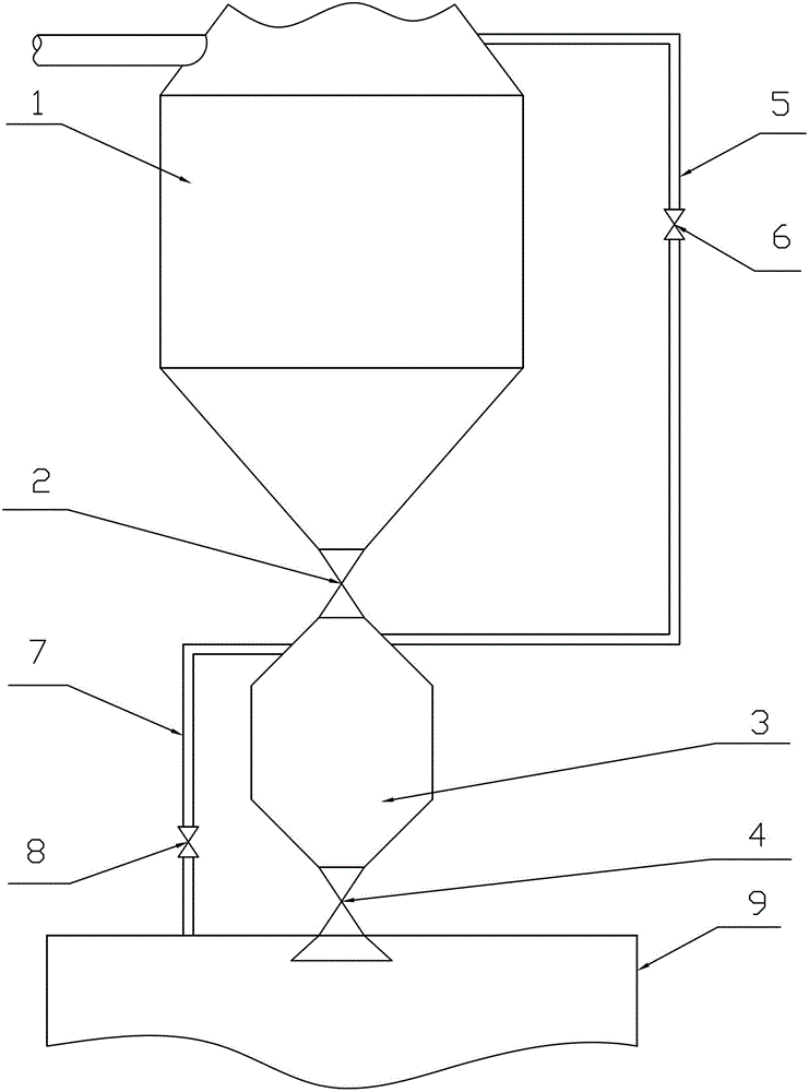
[0008] Refer to the attached figure 1 A non-pressure-difference ash-releasing device for a blast furnace gravity dust collector of the present invention will be described in detail below.

[0009] A non-pressure ash release device for a blast furnace gravity dust collector of the present invention, its structure includes a gravity dust collector 1, a ground ash bin 9 and an ash discharge valve, and the ash discharge valve includes an upper ash discharge valve 2 and a lower ash discharge valve 4 , an intermediate ash bin 3 is arranged between the gravity dust collector 1 and the ground ash bin 9, the upper ash valve 2 is arranged between the gravity dust collector 1 and the middle ash bin 3, and the lower ash valve 4 is arranged on Between the middle ash bin 3 and the ground ash bin 9, a pressure equalizing pipe 5 is arranged between the gravity dust collector 1 and the middle ash bin 3, and a pressure equalizing valve 6 is arranged on the pressure equalizing pipe 5. A release...


PUM

PropertyMeasurementUnit
dust removal efficiencyaaaaaaaaaa

Abstract

The invention belongs to a dust discharging device and particularly discloses a differential-pressure-free dust discharging device of a blast furnace gravity dust collector. The differential-pressure-free dust discharging device comprises a gravity dust collector body, a grounded dust bin and a dust discharging valve, wherein the dust discharging valve comprises an upper dust discharging valve and a lower dust discharging valve, a middle dust bin is arranged between the gravity dust collector body and the grounded dust bin, the upper dust discharging valve is arranged between the gravity dust collector body and the middle dust bin, the lower dust discharging valve is arranged between the middle dust bin and the grounded dust bin, a pressure equalizing pipeline is arranged between the gravity dust collector body and the middle dust bin, a pressure equalizing valve is arranged on the pressure equalizing pipeline, a diffusing pipeline is arranged between the middle dust bin and the grounded dust bin, and a diffusing valve is arranged on the diffusing pipeline. The differential-pressure-free dust discharging device of the blast furnace gravity dust collector has the advantages that by means of a two-stage dust discharging method, dust discharging differential pressure is eliminated, a gas flow velocity is substantially reduced, the abrasion of the dust discharging valve is substantially reduced, secondary dust raising pollution can be avoided during a dust discharging process, gas leakage can be reduced, safety hazards of operators can be reduced, power consumption of dust discharging machines can be reduced, and the like.

Description

technical field [0001] The invention relates to an ash-releasing device, in particular to a non-pressure-difference ash-releasing device for a blast furnace gravity dust collector in the iron and steel metallurgy industry. Background technique [0002] During the normal production process of the blast furnace, the raw coal gas formed contains a large amount of dust. These solid ash must be effectively collected and discharged. The primary collection device for the blast furnace dust is the blast furnace gravity dust collector. The gravity dust collector has a simple structure and high dust removal efficiency. Excellent performance, small resistance loss and other characteristics, the gravity dust collector is widely used in the dust removal system of blast furnace gas, and the dust removal efficiency can reach 80%. The amount of ash discharged through the gravity dust collector generally reaches about 16kg per ton of iron. According to the ironmaking production process, the...

Claims


Application Information

Patent Timeline
Patent Type & Authority Patents(China)
IPC IPC(8): C21B7/22
Inventor 刘进杨士岭高贤成周家梅高新运贾瑞民石静朱涛崔刚徐京义徐兆金胡尊彬马印亭曹洪志
Owner JIGANG GRP
Why Eureka
Try Eureka