Air heating furnace with nozzles in pre-burning chamber for reflowing preheating burning by opposed jetting and mixing

A technology of injection mixing and pre-combustion chamber, which is applied in furnaces, blast furnaces, heating furnaces, etc., can solve the problems of incomplete combustion, uneven mixing, large combustion chamber space, etc., and achieve the effect of increasing the local combustion temperature

Inactive Publication Date: 2012-11-07
ZHENGZHOU YUXING REFRACTORY MATERIAL
View PDF3 Cites 6 Cited by
  • Summary
  • Abstract
  • Description
  • Claims
  • Application Information

AI Technical Summary

Problems solved by technology

[0003] In view of the above situation, in order to overcome the defects of the prior art, the purpose of the present invention is to provide a hot air stove with nozzles in the pre-combustion chamber opposed to the injection mixed backflow preheating combustion, which can effectively solve the problem of low gas and air mixing rate, uneven mixing, and combustion intensity. Low temperature, low combustion temperature, incomplete combustion, large combustion chamber space and complex burner structure

Method used


Image

  • Air heating furnace with nozzles in pre-burning chamber for reflowing preheating burning by opposed jetting and mixing
  • Air heating furnace with nozzles in pre-burning chamber for reflowing preheating burning by opposed jetting and mixing
  • Air heating furnace with nozzles in pre-burning chamber for reflowing preheating burning by opposed jetting and mixing

Examples


Embodiment Construction

[0009] The specific implementation manners of the present invention will be described in detail below in conjunction with the accompanying drawings.

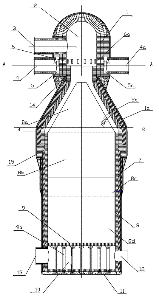
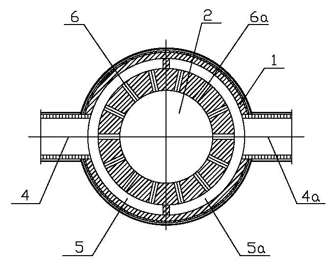
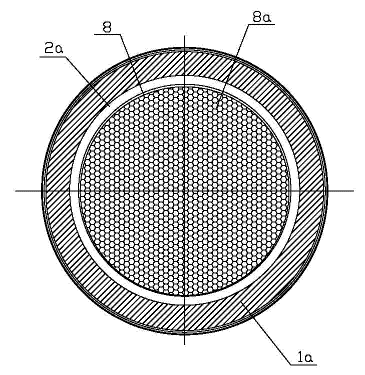
[0010] Depend on figure 1 , figure 2 and image 3 As shown, the present invention includes a pre-combustion chamber wall 1, a pre-combustion chamber 2, a combustion chamber wall 1a, a combustion chamber 2a, a hot air outlet pipe 3, a gas intake pipe 4, an air intake pipe 4a, a gas distribution loop 5, an air Distribution loop 5a, gas nozzle 6, air nozzle 6a, regenerator 8, regenerator, hot blast furnace wall 7, furnace grate 9, support column 9a, cold air chamber 10, cold air inlet pipe 12 and flue gas outlet pipe 13. The pre-chamber wall 1 is composed of the upper spherical vault and the lower cylinder. The space in the pre-chamber wall is the pre-chamber 2. The cylinder of the pre-chamber wall 1 is vertically The gas inlet pipe 4 and the air inlet pipe 4a are symmetrically arranged on the axis, and the gas inlet pipe and t...


PUM


Abstract

The invention relates to an air heating furnace with nozzles in a pre-burning chamber for reflowing preheating burning by opposed jetting and mixing. Gas and air inlet pipes on a pre-burning chamber wall are connected with gas and air distribution ring channels which are placed in half of the pre-burning chamber wall respectively, the nozzles on the ring channels are communicated with the pre-burning chamber in the pre-burning chamber wall, a hot air outlet pipe is arranged on the pre-burning chamber wall and connected with a burning chamber wall, a heat storage chamber is arranged on the lower portion of the burning chamber in the burning chamber wall, furnace grills and support columns are arranged on the lower portion of the heat storage chamber, heat retainers are arranged in the heat storage chamber, the support columns are placed in a cold air chamber, the heat storage chamber, the furnace grills and the cold air chamber are placed in an air heating furnace wall, the air heating furnace wall and a furnace bottom are fixed, a smoke outlet pipe and a cold air inlet pipe are arranged on the cold air chamber, and the air heating furnace wall is connected with the burning chamber wall in a sleeving mode. According to the air heating furnace, problems of low mixing rates, uneven mixing, low burning intensities, low burning temperatures, incomplete burning, unstable burning and complicated structures are solved.

Description

technical field [0001] The invention relates to a hot blast stove for preheating and combustion with nozzles in a pre-combustion chamber opposed to injection mixed backflow for providing high-temperature blast for a blast furnace. Background technique [0002] At present, considering energy saving and consumption reduction, blast furnace hot blast stoves are required to obtain high performance and high benefits under the combustion of low calorific value blast furnace gas, and finally achieve the goals of high efficiency, energy saving, environmental protection, and increased production. For this reason, an optimized combustion process must be combined with an enhanced heat transfer process in the hot blast stove. This involves the structure of the combustion device, the structure and arrangement of the heat storage body, and the organization of the air flow field. Looking at the various hot blast stoves currently in use, their gas combustion devices are mainly based on the...

Claims


Application Information

Patent Timeline
Patent Type & Authority Applications(China)
IPC IPC(8): C21B9/00
Inventor 陈云鹤杨海涛樊海强
Owner ZHENGZHOU YUXING REFRACTORY MATERIAL
Why Eureka
Try Eureka