
Device for measuring wave aberration of projection lens and method thereof

A technology of projection objective lens and wave aberration, which is applied in the direction of photographic plate-making process exposure device, test optical performance, micro-lithography exposure equipment, etc., can solve the problem of reducing measurement time-consuming time, and achieve the goal of reducing measurement time and total time Effect

Active Publication Date: 2012-11-07
SHANGHAI MICRO ELECTRONICS EQUIP (GRP) CO LTD
View PDF16 Cites 13 Cited by
  • Summary
  • Abstract
  • Description
  • Claims
  • Application Information

AI Technical Summary

Problems solved by technology

This method can not only improve the measurement accuracy of wave aberration but also reduce the measurement time

Method used


Image

  • Device for measuring wave aberration of projection lens and method thereof
  • Device for measuring wave aberration of projection lens and method thereof
  • Device for measuring wave aberration of projection lens and method thereof

Examples


Embodiment Construction

[0029] Specific embodiments of the present invention will be described in detail below with reference to the drawings.

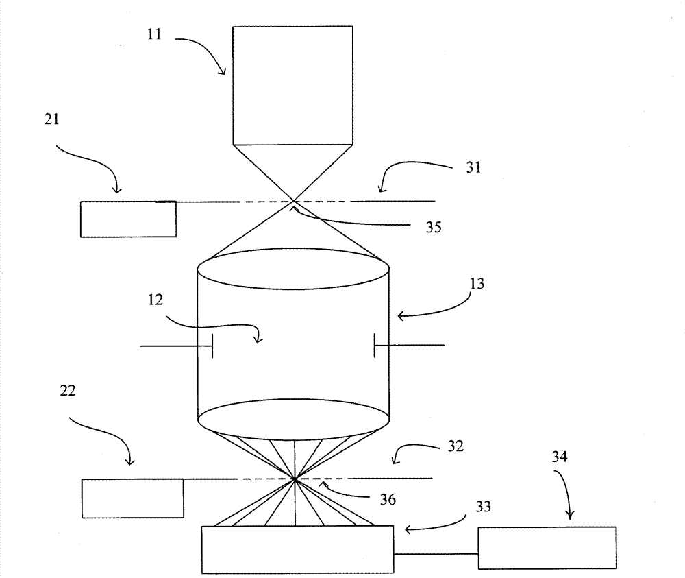
[0030] figure 1 It is a schematic diagram of the structure of an apparatus for measuring wave aberration of a projection objective according to the present invention. in figure 1 The device for measuring the wave aberration of the projection objective lens also includes a part of the lithography equipment. The device for measuring the wave aberration of a projection objective lens includes an object grating marking plate 31, an image grating marking plate 32, an image detector 33 and a data processing unit 34. The object surface grating mark plate 31 includes an object surface grating mark 35, and the image surface grating mark plate includes an image surface grating mark 36.

[0031] Lithography equipment is a kind of equipment used in integrated circuit manufacturing. The equipment can be used to produce or process including but not limited to: integrated circ...


PUM


Abstract

The invention discloses a device for measuring wave aberration of a projection lens. The device comprises: object plane rough measurement grating mark and precise measurement grating mark for generation of first diffracted lights; image plane grating mark containing image plane rough measurement grating mark and precise measurement grating mark; and an image detector. The diffracted lights generated from the object plane grating mark are gathered at the image plane grating mark by the projection lens, so as to generate secondary diffraction. Secondary diffracted lights generate interferograms in far field. According to the shearing interferograms measured by the image detector, the wave aberration of the projection lens is calculated. The invention simultaneously discloses the method for measuring the wave aberration of the projection lens.

Description

technical field [0001] The invention relates to the field of integrated circuit equipment manufacturing, in particular to a device and method for measuring the wave aberration of a projected objective lens suitable for photolithography equipment. Background technique [0002] One goal of the integrated circuit manufacturing industry is to integrate more electronic components into a single integrated circuit (IC). To achieve this goal, the size of the components must be continuously reduced, that is, the resolution of the lithography projection system must be continuously improved. As disclosed in patents EP1426824, EP1231514 and EP1439427, the wave aberration of the objective lens is an important factor limiting the resolution of the projection system, and it is an important cause of line width variation. [0003] Although the objective lens has been strictly inspected and optimized during the manufacturing and assembly process to minimize its wave aberration, it is still n...

Claims


Application Information

Patent Timeline
Patent Type & Authority Applications(China)
IPC IPC(8): G03F7/20G01M11/02
Inventor 马明英王帆
Owner SHANGHAI MICRO ELECTRONICS EQUIP (GRP) CO LTD
Learn More