Sowing machine based on automatic control system
An automatic control system and technology for planters, which are used in planter parts, fertilizers, planting equipment, and fertilization devices, can solve the problems of inability to detect the planting situation in real time, and inability to flexibly change the planting spacing and fertilizer amount, and achieve low prices. , the effect of improving the detection accuracy
- Summary
- Abstract
- Description
- Claims
- Application Information
AI Technical Summary
Problems solved by technology
Method used
Image

Examples
specific Embodiment approach 1
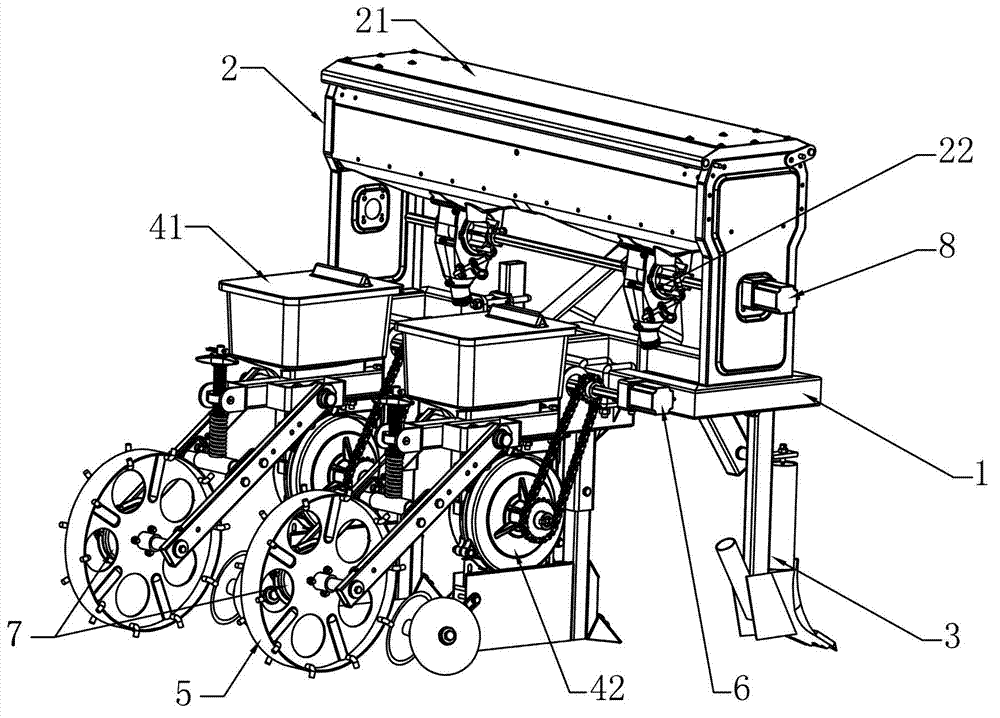
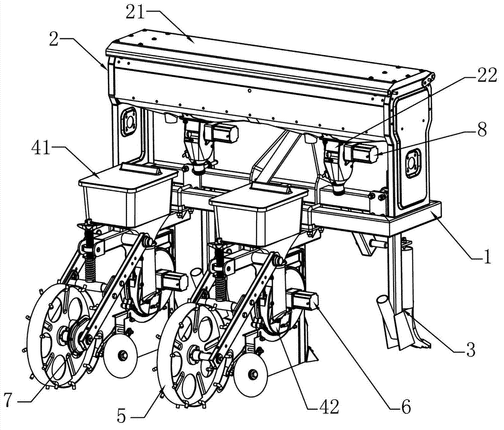
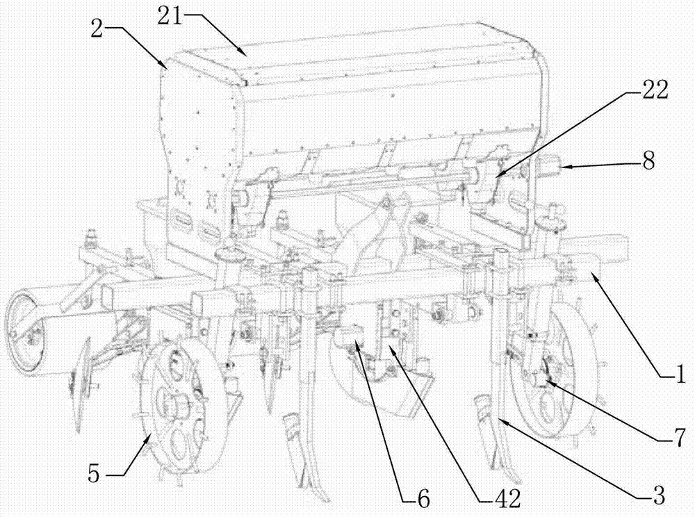
[0007] Specific implementation mode one: combine Figure 1 to Figure 10 Describe this embodiment, this embodiment comprises frame 1, fertilizer box 2, N soil lifting blades 3, N sowing units and ground wheel 5; The top of frame 1 is provided with fertilizer box 2, and fertilizer box 2 comprises fertilizer storage box 21 and N fertilizer discharge boxes 22, a fertilizer discharge box 22 is arranged on the fertilizer discharge port of the lower part of the fertilizer storage box 21, and the soil lifting shovel 3, fertilizer discharge box 22 and seeding unit are all sequentially arranged on the movement direction of the frame 1 , the forward direction facility of frame 1 has N soil lifting shovels 3, and the backward reverse direction facility of frame 1 has N sowing units, and described sowing unit comprises seed box 41 and seeder 42; Also comprises seeder Drive motor 6, photoelectric code disc 7, fertilizer discharge box drive motor 8, seed monitoring sensor 9 and controller, t...
specific Embodiment approach 2
[0009] Specific implementation mode two: combination Figure 6 Describe this embodiment, the difference between this embodiment and the above-mentioned specific embodiments is that the photoelectric code disc 7 includes a housing 71, a large gear 72, a pinion 73, a photoelectric encoder 74 and two rolling ball bearings 75; the housing 71 is buckled by two parts. Each part has a large round hole and a small round hole. The shaft hole of the large gear 72 is equipped with a bearing seat. The two rolling ball bearings 75 are respectively installed on the bearing seats on both sides of the large gear 72. Above, the two ends of the bearing seat pass through two large round holes of the housing 71 respectively, the large gear 72 and the pinion 73 are engaged, the signal collection shaft of the photoelectric encoder 74 passes through a small round hole of the housing 71, and the pinion 73 in turn. The shaft hole and another small circular hole of the housing 71 are coaxially connecte...
specific Embodiment approach 3
[0010] Specific implementation mode three: combination Figure 8 Describe this embodiment, the difference between this embodiment and the above-mentioned specific embodiment is that the seed monitoring sensor 9 includes a sensor housing 91 and a photoelectric counter 92, the four walls of the sensor housing 91 are opaque materials, and the upper end of the sensor housing 91 is open Closely matched with the outlet of the seed meter 42 , the photoelectric counter 92 is embedded in the housing of the sensor housing 91 . The seed monitoring sensor 9 is used to detect and record the number of seeds, and the seed monitoring sensor 9 is a photoelectric opaque object detection sensor, no matter soybean or corn seed, is an opaque object, which provides the possibility for the opaque object photoelectric detection sensor to detect the number of seeds; Composition and connection mode are the same as the above-mentioned specific embodiment.
PUM
 Abstract
Description
Claims
Application Information
 - Generate Ideas
- Intellectual Property
- Life Sciences
- Materials
- Tech Scout
- Unparalleled Data Quality
- Higher Quality Content
- 60% Fewer Hallucinations
Browse by: Latest US Patents, China's latest patents, Technical Efficacy Thesaurus, Application Domain, Technology Topic, Popular Technical Reports.
© 2025 PatSnap. All rights reserved.Legal|Privacy policy|Modern Slavery Act Transparency Statement|Sitemap|About US| Contact US: help@patsnap.com