Optimal control method for strip tail shear by flying shear at continuous annealing unit inlet

A continuous annealing unit, optimized control technology, applied to rolling mill control devices, metal rolling, manufacturing tools, etc., can solve problems such as complex control, and achieve the effect of reducing downtime

Active Publication Date: 2012-11-14
SHANGHAI BAOSIGHT SOFTWARE CO LTD +1
View PDF6 Cites 8 Cited by
  • Summary
  • Abstract
  • Description
  • Claims
  • Application Information

AI Technical Summary

Problems solved by technology

At the same time, the method disclosed in this patent application needs to constantly adjust the number of shears, and the control is relatively complicated.

Method used


Image

  • Optimal control method for strip tail shear by flying shear at continuous annealing unit inlet
  • Optimal control method for strip tail shear by flying shear at continuous annealing unit inlet
  • Optimal control method for strip tail shear by flying shear at continuous annealing unit inlet

Examples


Embodiment Construction

[0015] The present invention proposes an optimal control method for the shearing of the inlet flying shear and the tail of the continuous retreating unit, including:

[0016] Maintain the unit to convey the belt steel at a constant speed VL;

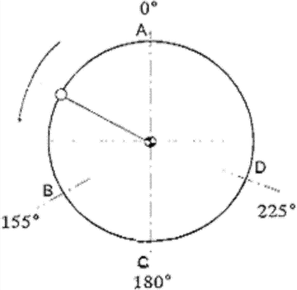
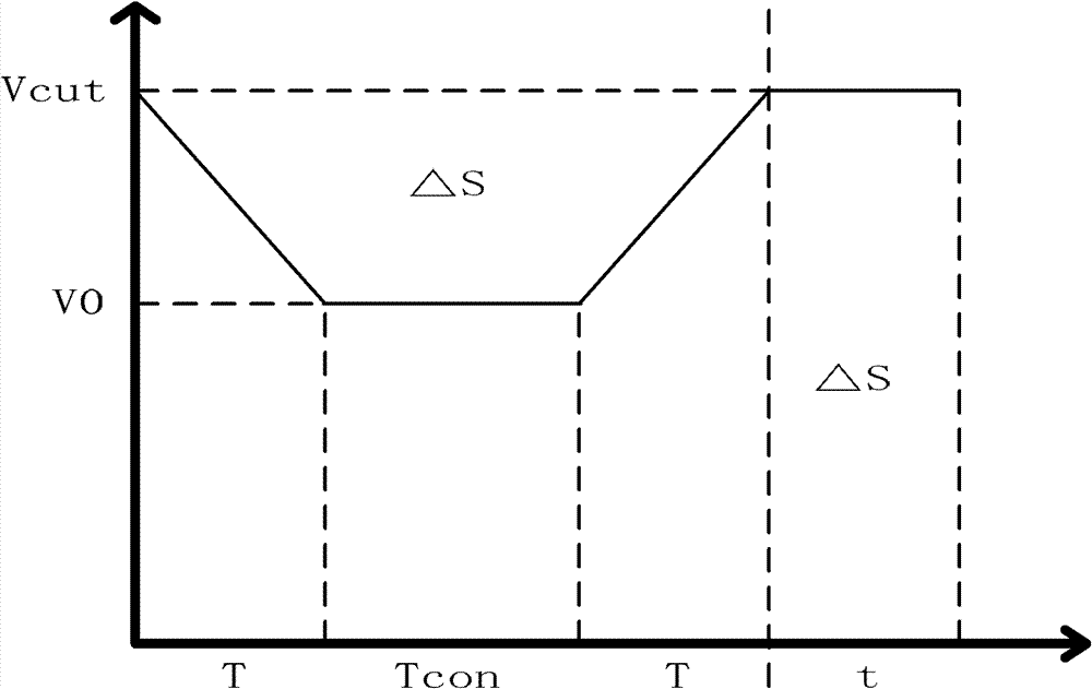
[0017] When performing belt-tail shearing, the flying shears are controlled to decelerate from the shearing speed Vcut with an acceleration A for a uniform deceleration time T, then run at a low speed and a constant speed for a time Tcon after deceleration, and then accelerate from the low speed with an acceleration A for a uniform time T to Vcut, so that The shear amount of the belt tail is increased by ΔL, so that the last piece of scrap steel strip at the belt tail falls into the scrap conveying system through the flying shears;

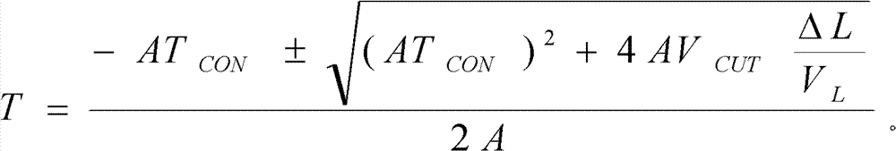
[0018] Where Tcon is determined according to ΔL, and the time T is calculated as follows:

[0019] T = - AT CON ...


PUM


Abstract

The invention discloses an optimal control method for strip tail shear by flying shear at a continuous annealing unit inlet. The method includes keeping a unit delivering strip steel at a constant speed VL; during strip tail shear, controlling the flying shear to evenly decelerate from a shearing speed Vcut at an acceleration A for T, operating at a low constant speed after the deceleration for Tcon, constantly accelerating from the low speed at the acceleration A for T to Vcut, so that the strip shearing amount is increased by delta L and the last waste strip steel of the strip tail falls into a waste transmitting system through the flying shear, wherein the Tcon is determined according to the delta L, and the calculation of the T is as follows. According to the method, variable speed control on the flying shear is performed through optimal calculation of the waste length, the last waste can fall into the waste transmitting system through the flying shear, and breakdown time of the unit can be effectively reduced.

Description

technical field [0001] The invention relates to the field of metallurgical automation, in particular to an optimization control method for the inlet flying shear and tail shear of a continuous annealing unit. Background technique [0002] The cutting of strip steel by flying shears is carried out within a certain angle of the crank. The position of the scissors when the upper and lower knives of the flying shears start to touch the strip depends on the angle of the lower knife on the one hand, and on the thickness and width of the strip on the other hand. The wider and thicker strips start to cut earlier. refer to figure 1 As shown, leaving the base point A, the flying shear accelerates. At point B where shearing begins, usually at 155°, the flying shears must reach the strip speed and begin shearing. When point C is reached, usually the 180° position, strip shearing is complete and the blades separate again. When point D is reached, usually at 225°, the gap between the...

Claims


Application Information

Patent Timeline
Patent Type & Authority Applications(China)
IPC IPC(8): B21B15/00B21B37/00C21D9/52C21D1/26
Inventor 徐文超张宝平包信方王梃黄才铨罗晓鹭黄佩杰陈允中肖萌萌
Owner SHANGHAI BAOSIGHT SOFTWARE CO LTD
Why Eureka
Try Eureka