Control system of laser moving track of rotating beam module group

A technology of rotating beam and motion trajectory, used in the fields of laser processing, cutting and drilling, and laser milling, it can solve the problems of inability to fill and rotate, difficult to control the processing effect, and large workload, and achieve easy filling and processing of solid circles and hole patterns. Good, high-quality edge effects

Active Publication Date: 2012-11-14
张立国
View PDF6 Cites 24 Cited by
  • Summary
  • Abstract
  • Description
  • Claims
  • Application Information

AI Technical Summary

Problems solved by technology

However, this laser rotation module itself can only make the laser rotate in a cylindrical surface or a conical surface, and cannot fill and rotate in a cylindrical ring or a conical ring. In fact, it is very limited in some processing, and needs to be combined with vibration The control of the mirror (patent application number: 201010183539.7) or the auxiliary realization of the platform movement, the workload is heavy and the processing effect is difficult to control

Method used


Image

  • Control system of laser moving track of rotating beam module group
  • Control system of laser moving track of rotating beam module group

Examples


Embodiment 1

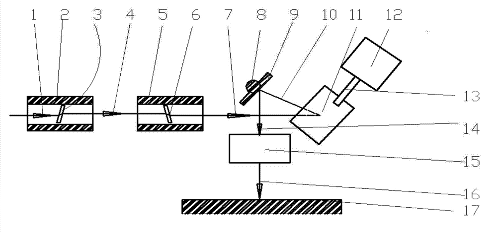
[0022] figure 1 Schematic diagram of the device structure for drilling stainless steel sheets, by figure 1 It can be seen that the laser motion trajectory control system of the rotating beam module group in the stainless steel sheet drilling includes incident light 1, the first rotating beam device cylinder 2, the second rotating beam device cylinder 5, the second reflecting mirror 9 of the vibrating mirror, and the motor of the vibrating mirror. 12. The first reflective mirror 11 of the vibrating mirror, the telecentric focusing mirror 15 and the workpiece 17 to be processed.

[0023] The workpiece 17 to be processed is a thin stainless steel plate with a thickness of 0.5 mm.

[0024] The incident light 1 is an incident expanded collimated beam with a diameter of 5 mm.

[0025] The first rotating beam device barrel 2 is provided with a flat sapphire glass 3, the thickness of the flat sapphire glass 3 is 0.5 mm, and it is obliquely arranged in the first rotating beam device ...

Embodiment 2

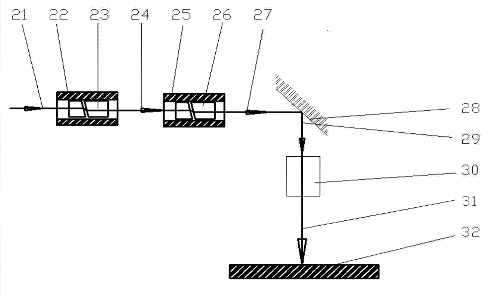
[0045] figure 2 Schematic diagram of the device structure for drilling ceramic blind vias, by figure 2 It can be seen that the laser movement trajectory control system of the rotating beam module group in ceramic blind hole drilling includes incident light 21, a first rotating beam device sleeve 22, a second rotating beam device sleeve 25, a laser reflective lens 28, a static focusing mirror 30 and The workpiece 32 to be processed.

[0046] The workpiece 32 to be processed is an alumina ceramic sheet with a thickness of 1 mm.

[0047] The incident light 21 is an incident expanded collimated light beam with a diameter of 5 mm.

[0048] The sleeve 22 of the first rotating beam device is provided with two opposing optical wedge assemblies 23 .

[0049] After the incident ray 21 passes through the first rotating beam device sleeve 22, a collimated output beam 24 is obtained, and the collimated output beam 24 is parallel to the incident ray 21, and the parallel distance betwe...


PUM

PropertyMeasurementUnit
diameteraaaaaaaaaa
thicknessaaaaaaaaaa
thicknessaaaaaaaaaa

Abstract

The invention belongs to the laser processing field, and discloses a control system of a laser moving track of a rotating beam module group. The control system includes that two or more than two rotating beam modules are connected in series, a last output beam completes revolution along the ray axis of a last rotating module incident light and performs rotation along the revolution track, and obtaining a focused beam through an optical focusing system, if a cross section of a fill movement track of a focusing point is a solid circle, flat top laser processing effects can be achieved by using Gaussian lasers, and laser processing characteristics of deep Gaussian laser telephoto and high Gaussian distribution light are provided; and if the cross section of the fill movement track of the focusing point is a ring, because the laser etched seam is wide, the spraying of material slag is facilitated, the processing efficiency and the processing quality are improved greatly, and the system is suitable for laser drilling and laser milling of certain crisp and hard materials; and if a rotating beam modules are locked, the laser recover narrow line wide leaser micromachining, and the application range of laser equipment is increased.

Description

technical field [0001] The invention belongs to the field of laser processing, especially the fields of laser milling, cutting and drilling. Background technique [0002] Rotating beam laser drilling technology In order to perform spiral drilling, a beam rotator is formed by using a rotating wedge prism or an off-axis rotating lens to realize the rotation of the laser beam. It can be installed on a hollow shaft driven high-speed motor. The laser beam is strictly adjusted. The high-speed rotating beam passes through the optical focusing system. The laser focus will rotate on the surface of the workpiece to process the required results. The workpiece is fixed on the two-dimensional mobile platform to realize large-format laser processing. However, this laser rotation module itself can only make the laser rotate in a cylindrical surface or a conical surface, and cannot fill and rotate in a cylindrical ring or a conical ring. In fact, it is very limited in some processing, and n...

Claims


Application Information

Patent Timeline
Patent Type & Authority Applications(China)
IPC IPC(8): B23K26/04B23K26/36B23K26/361B23K26/382
Inventor 张立国
Owner 张立国
Why Eureka
Try Eureka