Device of boiling chlorination furnace for continuous slagging and slagging method

A technology of boiling chlorination furnace and slag, applied in the direction of titanium halide, etc., can solve the problems of lack of sealing, controllable and continuous slag discharge technology of chlorination furnace, difficulty in realizing slag discharge rate control, and inability to discharge large particle slag, etc. Achieve the effect of improving reliability and operability, easy automatic control, and easy control

Active Publication Date: 2012-11-14
INST OF PROCESS ENG CHINESE ACAD OF SCI
View PDF9 Cites 16 Cited by
  • Summary
  • Abstract
  • Description
  • Claims
  • Application Information

AI Technical Summary

Problems solved by technology

The slag discharge technology has the following problems: (1) Since the slag discharge pipe is set in the middle of the fluidized fluidized furnace, the large particles of slag in the lower part of the furnace cannot be discharged, and after a certain period of time, it is still necessary to stop the furnace for intermittent slagging; (2) The slag discharge adopts automatic The overflow method lacks controllability; (3) Harmful gases such as chlorine gas entrained in the slag will still be discharged into the environment
This technology is suitable for intermittent slagging. If this device is used for continuous slagging, due to the large pressure difference between the inner (chlorination furnace) and the outer (sealed cover), a large amount of materials in the chlorination furnace will enter the sealed cover driven by the pressure difference. Difficult to control the slag discharge rate
[0008] To sum up, most of the slagging rate control of existing chlorination furnaces still relies on mechanical valves, and there is a lack of technology that does not use mechanical valves to realize the sealing, controllable and continuous slagging of chlorination furnaces

Method used


Image

  • Device of boiling chlorination furnace for continuous slagging and slagging method

Examples


Embodiment Construction

[0034] For better illustrating the present invention, facilitate understanding technical scheme of the present invention, typical but non-limiting embodiment of the present invention is as follows:

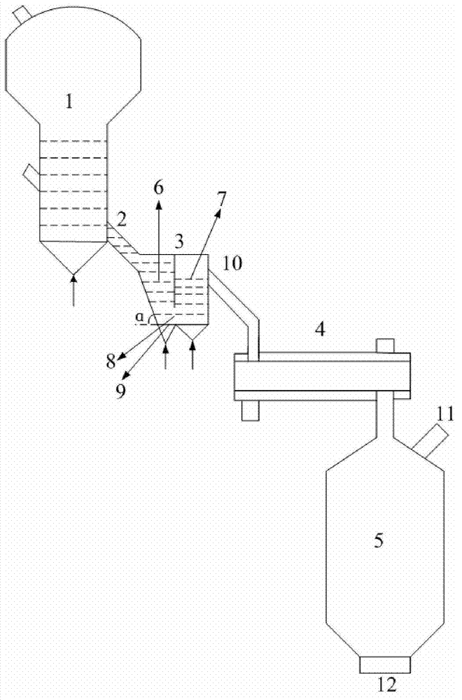
[0035] like figure 1 As shown, a continuous slagging device for a fluidized chlorination furnace, the device is composed of a slagging pipe 2, a slagging valve 3, a water-cooled screw slagging machine 4 and a slag tank 5 connected in sequence; the slagging pipe 2 Connect the bottom slag outlet of fluidized chlorination furnace 1. The slag discharge valve 3 includes a standpipe 6 and a discharge chamber 7 arranged side by side; the discharge chamber 7 communicates with the standpipe 6 through an orifice 8 at the bottom, and a discharge port 10 is provided on its upper part; One side of the pipe 6 is a slope; the bottom of the standpipe 6 and the discharge chamber 7 are respectively provided with air inlets, and a gas distribution plate 9 is arranged above the air inlets. The bott...


PUM


Abstract

The invention relates to a device of a boiling chlorination furnace for continuous slagging and a slagging method. The device is formed by a slagging pipe, a slagging valve, a water cooling spiral deslagging machine and a slagging tank that are sequentially connected through pipelines, the slagging valve comprises a vertical tube and a material discharge chamber that are in parallel, the material discharge chamber is communicated with the vertical tube through a hole at the bottom of the material discharge chamber, a material discharge opening is arranged at the upper part of the material discharge chamber, and the vertical tube and the bottom of the material discharge chamber are respectively provided with an air inlet. Slag forms stock columns in the vertical tube so that the device automatically seals, therefore, gas in the boiling chlorination furnace is prevented from leaking, slagging discharge rate is controlled through nitrogen flow regulation, and regulation and control of chlorination slagging rate are realized. According to the device, the boiling chlorination furnace realizes continuous slagging through a sealing and controllable manner without using a mechanical valve, therefore, the chlorination furnace is effectively prevented from leaking gas in the slagging process. The device has the advantages of being good in sealing performance, simple in operation, safe and reliable, easy to realize automatic control and the like.

Description

technical field [0001] The invention relates to the technical field of chemical industry and metallurgy, in particular to a continuous slagging device and a slagging method for a fluidized chlorination furnace. Background technique [0002] Titanium tetrachloride (TiCl 4 ) is the raw material for the production of titanium dioxide chloride and titanium metal. It is made of titanium-rich materials (titanium concentrate, rutile ore, artificial rutile, etc.) 2 Prepared by reacting with coke, the preparation reaction can be represented by the following reaction equation: [0003] TiO 2 +2C+2Cl 2 =TiCl 4 +2CO [0004] TiO 2 +C+2Cl 2 =TiCl 4 +CO 2 [0005] Titanium-rich materials usually also contain Fe 2 o 3 、Al 2 o 3 , SiO 2 , CaO, MgO, MnO, ZrO 2 、Cr 2 o 3 and other impurities. These impurities will also interact with Cl 2 and coke chlorination reaction to form FeCl 2 , FeCl 3 , AlCl 3 、SiCl 4 , CaCl 2 , MgCl 2 , MnCl 2 , ZrCl 4 , CrCl 3 and other b...

Claims


Application Information

Patent Timeline
Patent Type & Authority Applications(China)
IPC IPC(8): C01G23/02
Inventor 朱庆山李洪钟
Owner INST OF PROCESS ENG CHINESE ACAD OF SCI
Why Eureka
Try Eureka