Steel pipe concrete combined truss bridge

A technology for steel tube concrete and truss bridges, applied in truss bridges, bridges, bridge forms, etc., can solve the problems of high strength requirements for connecting steel plates, small connection surfaces, and limited connection capacity, so as to increase pullout resistance and reduce stress , Enhance the effect of shear resistance

Inactive Publication Date: 2012-11-14
ANHUI TRANSPORT CONSULTING & DESIGN INST
View PDF10 Cites 10 Cited by
  • Summary
  • Abstract
  • Description
  • Claims
  • Application Information

AI Technical Summary

Problems solved by technology

Since the former is a flat steel plate, the connection surface parallel to the steel pipe is small, which limits its connection capacity; the latter often uses multiple perforated steel plates, and the perforated plate connectors ar

Method used


Image

  • Steel pipe concrete combined truss bridge
  • Steel pipe concrete combined truss bridge
  • Steel pipe concrete combined truss bridge

Examples


Embodiment

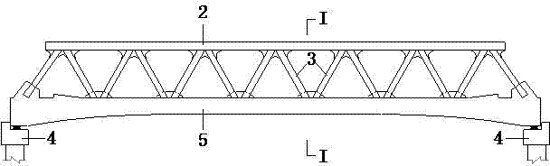
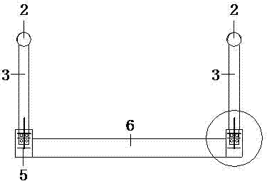
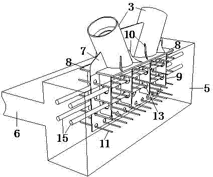
[0018] see figure 1 and figure 2 A steel tube concrete composite truss bridge includes piers 4 at both ends, a bridge deck 6, two parallel upper chords 2 and two parallel lower chords 5; The webs 3 are connected, and the evenly distributed webs 3 are connected sequentially in a W shape, that is, the lower end of one web corresponds to the lower end of the left adjacent web, and the upper end corresponds to the upper end of the right adjacent web; The root web 3 and the lower chord 5 are connected through the gusset plate 7 to form the lower chord node; see image 3 and Figure 4 , the middle of the upper part of the gusset plate 7 runs through two adjacent web members 3, the lower part is located at the lower chord 5, and the lower part of the gusset plate 7 is uniformly provided with reinforcement holes, and the reinforcement holes are provided with shear reinforcement bars 11, including two The longitudinal prestressed steel beam 15 of the lower chord above. At the node...


PUM


Abstract

The invention relates to a steel pipe concrete combined truss bridge. The combined truss bridge comprises piers at two ends, a bridge panel, two upper parallel chord members and two lower parallel chord members, wherein the upper chord members and the lower chord members which vertically correspond to each other are connected through uniformly distributed web members which are sequentially connected in a W shape; parallel connecting steel plates are arranged at the peripheries of two web members at the joints of the lower chord members of the combined truss bridge; reinforcing ribs connected with the upper surfaces of the connecting steel plates are uniformly distributed at the periphery of each web member; vertical reinforcing steel plates in vertically downward state are uniformly distributed on the lower surfaces of the connecting steel plates, and positioned at the lower chord members; steel beam holes are uniformly formed in each vertical reinforcing steel plate; and longitudinal prestressing steel beams of the lower chord members pass through the steel beam holes in the vertical reinforcing steel plates. Compared with traditional connecting joint of steel rod and concrete plate, the steel pipe concrete combined truss bridge is more reliable in connecting, and the joint is simply manufactured and convenient to construct.

Description

technical field [0001] The invention belongs to the technical field of bridges, in particular to a steel tube concrete composite truss bridge. Background technique [0002] The steel tube concrete composite truss bridge makes full use of the tensile resistance of steel and the compression resistance of concrete. The combined performance exceeds the superposition of the properties of the two materials. Well-arranged nodes on the surface. The perforated plate connector is to insert a perforated steel plate into the concrete as a connector between the steel rod and the concrete. It is one of the commonly used connector forms for the connection between the steel rod and the concrete, because the perforated plate connector has many advantages. : 1. The hole processing on the steel plate is simple; 2. The shear rigidity is relatively large, and it will be further increased when the shear reinforcement is set in the round hole; 3. The concrete in the round hole is used to resist t...

Claims


Application Information

Patent Timeline
IPC IPC(8): E01D6/00
Inventor 王吉双席进梁长海吴平平王诗青魏民戴玮袁瑞
Owner ANHUI TRANSPORT CONSULTING & DESIGN INST
Why Eureka
Try Eureka