Rectangular waveguide directional coupler

A technology of directional coupler and rectangular waveguide, which is applied in the direction of waveguide devices, electrical components, connecting devices, etc., can solve the problems of high insertion loss, reduced directivity, and narrow bandwidth, and achieve large power capacity, low insertion loss, and increased directional effect

Inactive Publication Date: 2012-11-14
成都赛纳赛德科技有限公司
View PDF3 Cites 101 Cited by
  • Summary
  • Abstract
  • Description
  • Claims
  • Application Information

AI Technical Summary

Problems solved by technology

[0005] The traditional single-hole directional coupler has some advantages: such as simple structure, few parameters, and it is more convenient to design; but it also has some disadvantages: such as narrow bandwidth and poor directivity, it is only suitable for working at the design frequency, and it deviates from this frequency , the directionality will decrease
[0006] Although the tradition

Method used


Image

  • Rectangular waveguide directional coupler
  • Rectangular waveguide directional coupler
  • Rectangular waveguide directional coupler

Examples


Embodiment 1

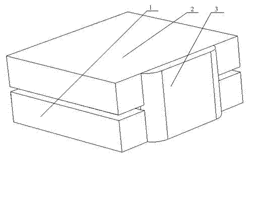
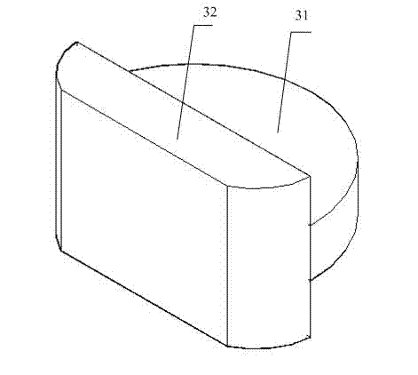
[0044] Such as Figure 4 , 5 As shown, this embodiment includes a main rectangular waveguide 1 and a sub-rectangular waveguide 2. The main rectangular waveguide 1 is a microwave main channel, and the sub-rectangular waveguide 2 is a sampling signal channel; the main rectangular waveguide 1 and the sub-rectangular waveguide 2 have main modes H The surfaces are parallel to each other, the main rectangular waveguide 1 and the auxiliary rectangular waveguide 2 are isolated from each other, and there is a coupling hole 3 including a hollow coupling tube 32 attached to the side wall of the main rectangular waveguide 1 or the side wall of the auxiliary rectangular waveguide 2. 32. The side wall close to the rectangular waveguide 1 is connected to a three-end open coupling cavity 31. The coupling cavity 31 is connected to the hollow coupling tube 32. The coupling cavity 31 is located between the main rectangular waveguide 1 and the auxiliary rectangular waveguide 2 and is connected to th...

Embodiment 2

[0046] Such as Image 6 As shown, the difference from the first embodiment is that the main rectangular waveguide 1 and the secondary rectangular waveguide 2 are parallel, and there is no angle. The coupling holes 3 are only partly inside the main rectangular waveguide 1 and the sub-rectangular waveguide 2, and partly outside. No columnar metal body 7 is provided in the coupling hole 3.

Embodiment 3

[0048] Such as Figure 7 As shown, the difference from the first embodiment is that the main rectangular waveguide 1 and the sub-rectangular waveguide 2 are connected through two coupling holes 3, and the centers of the two coupling holes 3 are respectively located at the intersection of the main rectangular waveguide 1 and the sub-rectangular waveguide 2 Near the two opposite vertices of the parallelogram.


PUM


Abstract

The invention discloses a rectangular waveguide directional coupler. The rectangular waveguide directional coupler comprises a main rectangular waveguide serving as a main microwave channel, a sub-rectangular waveguide serving as a sampling signal channel, and coupling holes serving as coupling channels, wherein the main mode H-surface of the main rectangular waveguide is parallel to that of the sub-rectangular waveguide; the main rectangular waveguide is isolated from the sub-rectangular waveguide; the main rectangular waveguide is communicated with the sub-rectangular waveguide through one or two coupling holes; at least one coupling hole includes a hollow coupling pipe attached with the sidewall of the main rectangular waveguide or/and the sidewall of the sub-rectangular waveguide; the sidewall of the hollow coupling pipe close to the rectangular waveguide is connected with a coupling cavity with three opening ends; and the coupling cavity is communicated with the hollow coupling pipe, and is located between and communicated with the main rectangular waveguide and the sub-rectangular waveguide. The rectangular waveguide directional coupler provided by the invention is compact in structure and easy in processing, and has the outstanding advantage of low insertion loss in comparison with the common single-hole directional coupler, particularly in the millimeter wave band and the Terahertz wave band.

Description

technical field [0001] The invention relates to a rectangular waveguide directional coupler, in particular to a rectangular waveguide directional coupler coupled by single or double holes. Background technique [0002] The directional coupler is a microwave device widely used in the microwave system. Its main function is to distribute the power of the microwave signal in a certain proportion; the directional coupler is composed of two transmission lines, coaxial line, rectangular waveguide, circular waveguide, Both striplines and microstrip lines can form directional couplers; so from the structure point of view, there are many types of directional couplers with great differences, but from the perspective of their coupling mechanism, they are mainly divided into four types, namely small hole coupling, parallel coupled, branch coupled, and matched double-T. [0003] Before the early 1950s, almost all microwave equipment used metal waveguides and waveguide circuits, and the ...

Claims


Application Information

Patent Timeline
IPC IPC(8): H01P5/18
Inventor 王清源谭宜成
Owner 成都赛纳赛德科技有限公司
Why Eureka
Try Eureka