Multiple-frequency-band antenna device for near field communication and application system thereof

A multi-band antenna and short-distance technology, which is applied in the near-field transmission system, enables the antenna to work in different bands of devices and antennas at the same time, can solve the problems of increasing the area and volume of POS machines, and achieve volume and area reduction, The operation is convenient and convenient, and the effect of swiping the card is maintained

Inactive Publication Date: 2012-11-14
NATIONZ TECH INC
View PDF3 Cites 18 Cited by
  • Summary
  • Abstract
  • Description
  • Claims
  • Application Information

AI Technical Summary

Problems solved by technology

In the market state where multiple schemes coexist, at this stage, some POS machine manufacturers connect the card reader modules of the two different schemes, set different card swiping transaction positions and reminder signs to realize the card swiping needs of different users, which will inevitably lead to user Before swiping the card, it is necessary to judge the technical solution adopted by the card held and the inconvenience of the corresponding swiping area, and at the same time, it will increase the area and volume of the POS machine due to the setting of multiple card swiping areas

Method used


Image

  • Multiple-frequency-band antenna device for near field communication and application system thereof
  • Multiple-frequency-band antenna device for near field communication and application system thereof
  • Multiple-frequency-band antenna device for near field communication and application system thereof

Examples


Embodiment 1

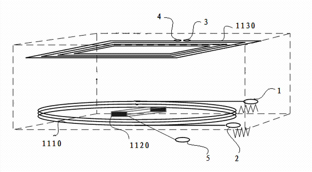
[0056] Embodiment 1: as figure 2 As shown, a stacked structure is adopted, the 13.56MHz antenna module 1130 is on the top layer, the low-frequency magnetic coupling coil 1110 is directly below it, and the 2.4GHz radio frequency antenna module 1120 is located in the middle of the shape surrounded by the low-frequency magnetic coupling coil 1110, in order to shield the low-frequency magnetic induction coil For the interference of 1110 on 13.56MHz antenna module 1130, a certain distance between 13.56M antenna module 1130 and low-frequency magnetic induction coil 1110, 1mm to 10mm is feasible, so as to realize the closed loop of 13.56MHz magnetic field lines and the outward radiation of energy.

Embodiment 2

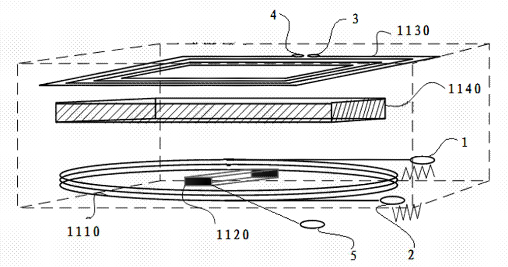
[0057] Embodiment 2: as image 3 As shown, the difference between this embodiment and Embodiment 1 is that an anti-jamming device 1140 is provided between the 13.56 MHz antenna module 1130 and the low-frequency magnetic coupling coil 1110, and the anti-jamming device 1140 uses a wave-absorbing material in the 13.56 MHz frequency band Or it is made of magnetically permeable material that acts as a magnetic conductor for the 13.56MHz magnetic field, such as ferrite, so as to realize the closed loop of the 13.56MHz magnetic force line and the outward radiation of energy.

Embodiment 3

[0058] Embodiment 3: as Figure 4 As shown, the difference between this embodiment and Embodiment 1 and Embodiment 2 is that a tiled structure is adopted, the 13.56MHz antenna module 1130 is on the outermost layer, the low-frequency magnetic coupling coil 1110, the 13.56M antenna module 1130 and the 2.4GHz radio frequency antenna module 1120 are on the same plane, and the low-frequency magnetic coupling coil 1110 is separated from the 13.56MHz antenna module 1130 by a certain distance. Most of the magnetic field radiated by 1130 passes through the gap, and the radiation energy blocked by the low-frequency magnetic coupling coil 1110 is quite small, so that the energy of the 13.56MHz antenna module 1130 can radiate out without a blind area.

[0059] The 13.56MHz antenna module 1130 and the low-frequency magnetic coupling coil 1110 may not be on the same plane, but the 13.56MHz antenna module 1130 is located at a position not shielded by the low-frequency magnetic coupling coil ...


PUM


Abstract

The invention relates to a multiple-frequency-band antenna device for near field communication. The multiple-frequency-band antenna device comprises an interface module, a low-frequency magnetic coupling coil, a 13.56MHz antenna module and a 2.4GHz radio-frequency antenna module, wherein the low-frequency magnetic coupling coil, the 13.56MHz antenna module and the 2.4GHz radio-frequency antenna module are connected with the interface module. An interval exists between the low-frequency magnetic coupling coil and the 13.56MHz antenna module, and the low-frequency magnetic coupling coil is connected with a main control device through the interface module and sends a low-frequency alternating magnetic field to transmit data to a mobile communication terminal. The 13.56MHz antenna module emits a radio-frequency signal, is connected with the main control device through the interface module, and carries out data interaction with the mobile communication terminal. The 2.4GHz radio-frequency antenna module is connected with the main control device through the interface module and carries out data interaction with the mobile communication terminal. The multiple-frequency-band antenna device has the beneficial effects that users can operate fast and conveniently, and the multiple-frequency-band antenna device is more easily popularized.

Description

technical field [0001] The invention relates to the field of short-distance wireless communication, in particular to a short-distance communication multi-band antenna device and an application system thereof. Background technique [0002] In the existing mobile payment technology, in order to realize short-distance safe payment transactions, the main solutions are: 13.56MHz-based non-contact technology and NFC (Near Field Communication, short-distance wireless communication technology) technical solutions and 2.4GHz-based RFID-SIM solutions . The NFC technical solution is that the working frequency band is 13.56MHz, and the card reader device transmits and receives data through the 13.56MHz antenna to realize the transaction between the card reader and the mobile terminal. The 2.4GHz-based RFID-SIM solution uses low-frequency magnetic coupling coils and 2.4G radio frequency antennas to realize short-distance wireless reception and data transmission to realize card swiping t...

Claims


Application Information

Patent Timeline
Patent Type & Authority Applications(China)
IPC IPC(8): H01Q1/36H01Q5/01H04B5/00H01Q5/10
CPCH01Q7/00H04B5/0081H01Q5/0072H01Q5/40
Inventor 王根平
Owner NATIONZ TECH INC
Why Eureka
Try Eureka