Method for producing a carbon brush in a commutator

A commutator, carbon brush technology, applied in brush manufacturing, current collectors, rotary current collectors, etc., can solve the problems of carbon brush resistance increase and change, etc.

Inactive Publication Date: 2012-11-14
ROBERT BOSCH GMBH
View PDF4 Cites 0 Cited by
  • Summary
  • Abstract
  • Description
  • Claims
  • Application Information

AI Technical Summary

Problems solved by technology

However, it should be noted that carbon brushes made of sintered materials have a large number of pores due to the construction method. Due to these pores, the carbon brush material is more susceptible to the external environment, and the influence of environmental conditions will cause the material of the carbon brush to develop Changes, especially lead to increased carbon brush resistance

Method used


Image

  • Method for producing a carbon brush in a commutator

Examples


Embodiment Construction

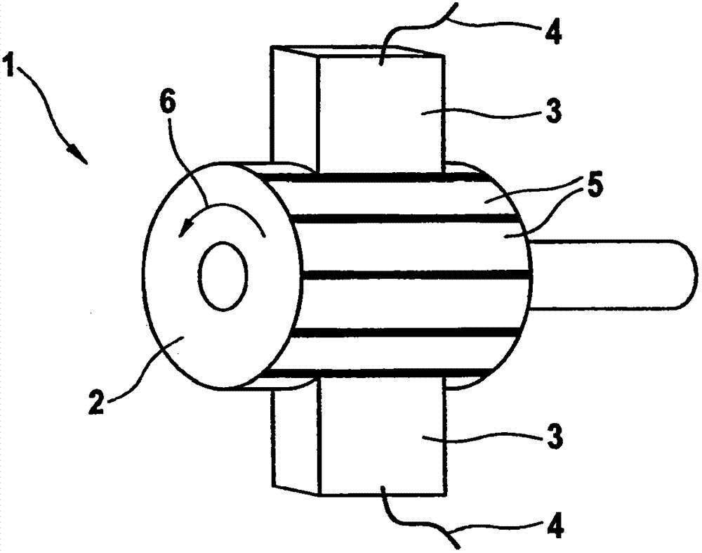
[0017] figure 1 The current collector 1 shown is used for the transmission and commutation of electric current in an electric machine, such as an electric motor or a generator, and is preferably used for a starter of an internal combustion engine. Such starters are designed for extensive starting operations, especially in the case of motor vehicles equipped with a start-stop system for automatically switching off and switching on the internal combustion engine.

[0018] The commutator 1 comprises a cylindrical current collector 2 which is non-rotatably connected to the armature of the electric machine, the armature being rotatably mounted in the stator. Furthermore, the commutator 1 comprises a plurality of carbon brushes 3 which, in the exemplary embodiment shown, are in contact with diametrically opposite radially outer peripheral surfaces or a The rolling surface of the disk transmits the current introduced into the corresponding carbon brush 3 via the twisted wire 4 to th...


PUM


Abstract

The invention relates to a method for producing a carbon brush in a commutator for transmitting current in an electric motor, wherein the carbon brush is subjected to an artificial aging process after being produced and prior to being installed in the commutator, wherein the carbon brush is stored at an increased temperature for a defined period of time.

Description

technical field [0001] The invention relates to a method for producing carbon brushes in a commutator for transmitting current in an electric machine. Background technique [0002] The commutator is used in electric motors to transmit current to an armature mounted in rotation in the stator and to change the direction of the current when the armature coils are short-circuited. The commutator consists of a current collector on the armature side and carbon brushes fastened to the housing, which rest against the circumference of the rotating current collector. [0003] A carbon brush for small electric machines is known from DE 4025367 C2, which is made of graphite powder which is mixed with metal powder, pressed and subsequently sintered. For example, copper is mixed as metal component in such carbon brushes. [0004] The current collectors and carbon brushes are subject to wear during the operation of the motor. The amount of wear must be designed according to the purpose ...

Claims


Application Information

Patent Timeline
IPC IPC(8): H01R39/26H01R43/12
CPCH01R43/12H01R39/26
Inventor M·拜尔M·希克
Owner ROBERT BOSCH GMBH
Why Eureka
Try Eureka