Rolling type buffer bed

An impact bed, rolling technology, applied in the field of impact bed, can solve the problems of increased energy consumption, increased overall cost, belt conveyor resistance, etc., to achieve the effects of small resistance, reduced material strength, and reduced overall cost

Inactive Publication Date: 2012-11-21
HUNAN YINGHONG SCI & TECH
View PDF7 Cites 4 Cited by
  • Summary
  • Abstract
  • Description
  • Claims
  • Application Information

AI Technical Summary

Problems solved by technology

The buffer idler is equipped with a lot of rubber buffer rings on the outer surface of the steel idler. Its disadvantages are: the thickness of the buffer rubber ring is thin, the buffer effect is poor, and the density of the installed idlers is small, so that most of the belts are suspended state, the strength is not enough; although the sliding buffer bed overcomes the shortcomings of the buffer roller, that is, it has a good buffer effect and sufficient strength, but there is sliding friction at the contact part of the conveyor belt and the bed body, and the belt conveyor belt If there is a lot of resistance, the power of the power source driving the belt conveyor should be relatively increased, so that the energy consumption will increase, and the strength of other components must also increase, which increases the overall cost.

Method used


Image

  • Rolling type buffer bed
  • Rolling type buffer bed
  • Rolling type buffer bed

Examples


Embodiment Construction

[0013] The specific implementation manners of the present invention will be further described in detail below in conjunction with the accompanying drawings.

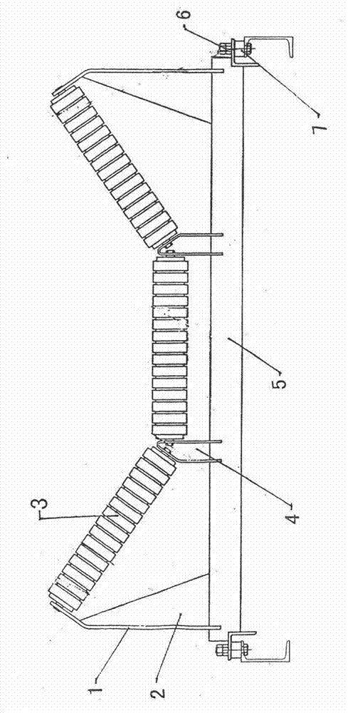
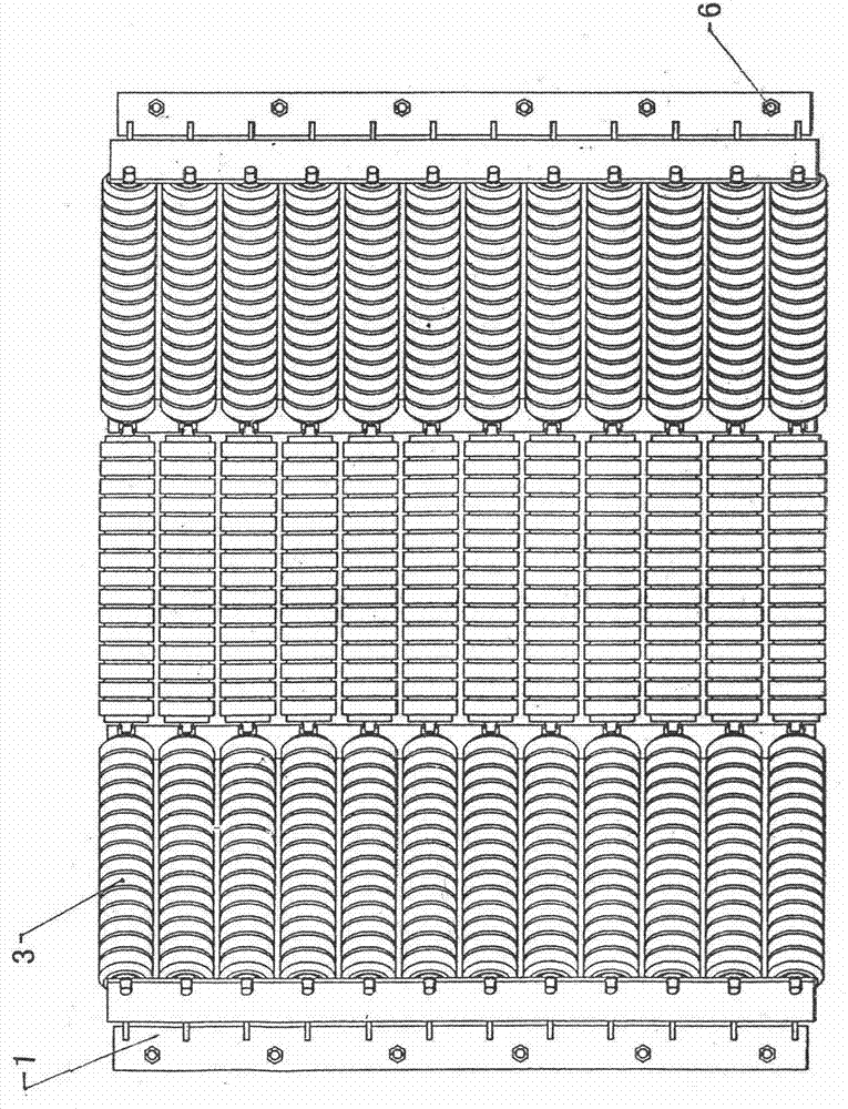
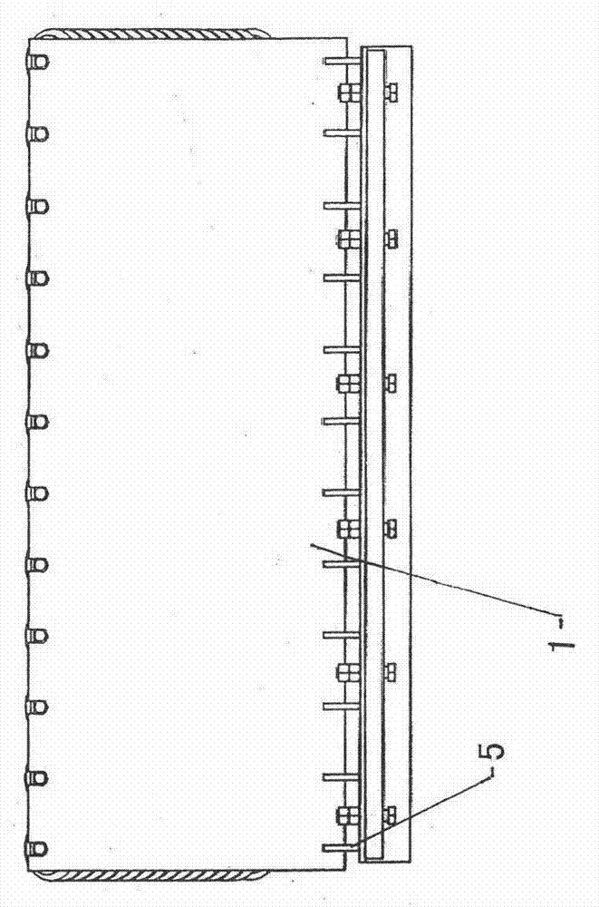
[0014] As shown in the accompanying drawings, the rolling impact bed includes a side support 1, a rib plate 2, a buffer roller 3, a middle support 4, a bed 5, a bolt group 6 and a buffer pad 7, and the bolt group 6 It is usually composed of bolts and gaskets (rings), known technology, and the bed 5 is an integral body made of neatly arranged steel plates with a quantity greater than 1 and angle steel welded at both ends of the steel plate, which ensures the stability of the rolling impact bed. The two ends of the bed 5 are connected with the legs through the bolt group 6 and the buffer pad 7, wherein the buffer pad 7 is made of rubber material and has an elastic function. The two ends of the upper surface of the bed 5 are symmetrically fixed with side brackets 1, the heights of each side bracket 1 are the same, and the r...


PUM


Abstract

The invention discloses a rolling type buffer bed. A bed body (5) is connected with supporting legs through a bolt set (6) and a buffer pad (7) at the two ends of the bed body (5); side brackets (1) with the same height are symmetrically and fixedly connected at the two ends on the upper surface of the bed body (5); more than one rib plate (2) is close to the inner side of each side bracket (1) and fixedly connected to the four corners on the upper surface of the bed body (5); more than one middle bracket (4) with the same height is symmetrically arranged in the middle close to the bed body (5); and the two ends of each of more than one buffer supporting roller (3) are movably connected to the upper end between each side bracket (1) and each middle bracket (4) and the two ends of each buffer supporting roller are movably connected to the upper end between the symmetrically distributed middle brackets (4). The more than one buffer supporting roller (3) is regularly mounted between each side bracket (1) and each middle bracket (4) and between the two middle brackets, so that a conveyer belt is uniformly in contact with the buffer supporting rollers (3), the buffer effect is enhanced, the working life of the buffer supporting rollers (3) is prolonged, and the dual-buffer effect is achieved due to the effect of the buffer pad (7). Therefore, the rolling type buffer pad is energy-saving, high in strength and stable in operation, and has practical and promotional values.

Description

technical field [0001] The invention relates to a buffer bed, in particular to a rolling buffer bed at the feeding point of a belt conveyor for conveying powdery materials or massive materials. Background technique [0002] At present, due to the strong impact of blanking (such as powdered iron ore powder or lump coke, dolomite or limestone, etc.) on the blanking point (place) on the belt conveyor, the idler roller or bracket group is easily damaged. This is usually provided with a buffer device on the roller or bracket of the blanking part, such as a buffer roller or a sliding buffer bed is an example. The buffer idler is equipped with a lot of rubber buffer rings on the outer surface of the steel idler. Its disadvantages are: the thickness of the buffer rubber ring is thin, the buffer effect is poor, and the density of the installed idlers is small, so that most of the belts are suspended state, the strength is not enough; although the sliding buffer bed overcomes the sho...

Claims


Application Information

Patent Timeline
IPC IPC(8): B65G15/60B65G39/12
Inventor 杨建民
Owner HUNAN YINGHONG SCI & TECH
Why Eureka
Try Eureka