
Electromagnetic paraffin-inhibiting viscosity reducer

An electromagnetic anti-waxing and viscosity-reducing technology, which is used in cleaning equipment, wellbore/well components, and earth-moving drilling and mining, etc., can solve the problem that the electromagnetic anti-waxing and viscosity-reducing device is not versatile enough, cannot be adjusted for changes, and the sealing material is easy to fail. and other problems, to achieve the effect of prolonging the pump inspection and pipeline wax cleaning cycle, preventing wax precipitation, and improving oil production and pipeline transportation efficiency.

Inactive Publication Date: 2012-11-21
上海减速机械厂有限公司
View PDF8 Cites 9 Cited by
  • Summary
  • Abstract
  • Description
  • Claims
  • Application Information

AI Technical Summary

Problems solved by technology

However, the magnetic anti-wax viscosity reduction technology has the following disadvantages: First, the parameters such as the magnetic field strength of the current domestic magnetic anti-wax device cannot be adjusted with the change of the well conditions, which leads to the production of the electromagnetic anti-wax viscosity reduction device. The disadvantage of poor versatility; second, the current domestic magnetic anti-wax device only uses waterproof material to seal the induction coil, because the electromagnetic anti-wax viscosity reducer is used in the open air, the temperature difference is large, and the sealing material is prone to failure; third, the current domestic The magnetic anti-wax device only pays attention to the establishment of the magnetic field, but ignores the best relationship between the magnetic field and the temperature. Therefore, the general viscosity reduction effect is not good, especially in low permeability oil wells.

Method used


Image

  • Electromagnetic paraffin-inhibiting viscosity reducer
  • Electromagnetic paraffin-inhibiting viscosity reducer
  • Electromagnetic paraffin-inhibiting viscosity reducer

Examples


Embodiment Construction

[0020] In order to make the present invention more comprehensible, a preferred embodiment is described in detail below with accompanying drawings.

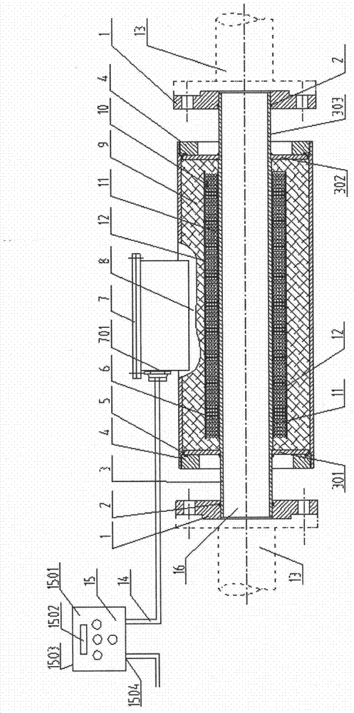
[0021] figure 1 It is a schematic diagram of an electromagnetic wax-preventing viscosity reducer provided by the present invention. The electromagnetic wax-prevention viscosity reducer includes a magneto-thermal generator 16 , and the power control box 15 is connected to the magneto-thermal generator 16 through a cable 14 .

[0022] The power control box 15 is composed of a power conversion control circuit board 1501 installed in the electric box shell 1503 , a control display panel 1502 , and wiring terminals 1504 inside the box. The terminal 1504 in the box is connected to one end of the cable 14 , and the control display panel 1502 is connected to the terminal 1504 in the box through the power conversion control circuit board 1501 .

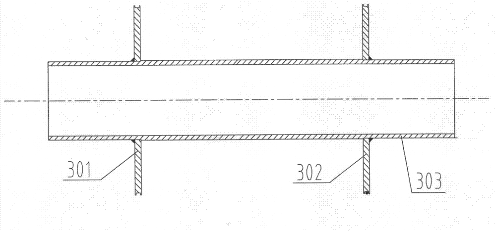
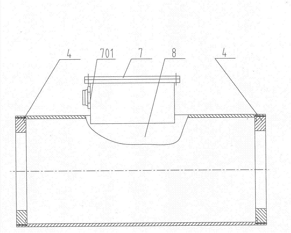
[0023] The magnetic heat generating device 16 includes an inner tube 3, and the coil 6 is wou...


PUM


Abstract

The invention provides an electromagnetic paraffin-inhibiting viscosity reducer comprising a power supply control cabinet and a magneto-calorific generator which are connected with each other through a cable. The electromagnetic paraffin-inhibiting viscosity reducer is characterized in that the magneto-calorific generator comprises an inner tube, a coil is wound on the external circle of the inner tube, and a temperature sensor is arranged in the outermost layer of the coil; a housing is arranged outside the inner tube, end screw plates are arranged at two ends of the housing, and a junction box is arranged at the external circle of the housing and connected with the coil, the temperature sensor and one end of the cable. According to the electromagnetic paraffin-inhibiting viscosity reducer provided by the invention, the defect of the prior art is overcome, a certain electromagnetic force and temperature can be generated, the crude oil flowing through the electromagnetic paraffin-inhibiting viscosity reducer can be physically modified, the wax precipitation and the deposition of crude oil in the tube are prevented, the viscosity of the crude oil is reduced, and thus, the oil extraction yield and the pipeline transport efficiency are increased, and the periods of pump detection and pipeline paraffin cleaning are prolonged.

Description

technical field [0001] The invention relates to an electromagnetic anti-wax viscosity reducer, which belongs to the technical field of crude oil exploitation and pipeline transportation. Background technique [0002] Most of the crude oil produced in my country's oilfields has a high wax content. In particular, the crude oil produced in northern my country is paraffin-based crude oil with "high wax content, high viscosity, and high freezing point". In the process of oilfield exploitation, with the change of temperature, pressure, flow velocity, gas and other conditions, wax crystals in crude oil begin to precipitate and combine with colloid, asphalt, etc. to form wax deposition. If the deposited paraffin adheres to the inner wall of the wellbore and surface pipeline, it will increase the flow resistance of crude oil, reduce the effective flow area, reduce the production of the oil well, and even lead to production shutdown. [0003] Therefore, each oil field must consume a...

Claims


Application Information

Patent Timeline
IPC IPC(8): E21B37/00
Inventor 乔华山李国亮
Owner 上海减速机械厂有限公司
Learn More