

Dry flow test method and test device
A technology of a test device and a test method, applied in the field of mechanical engineering, can solve the problems that the product cleanliness index is not easy to meet the standard, pollute the production environment of workstation appliances, inconvenient storage, transportation and assembly, etc., and achieves short test period, low cost, and convenient transportation. Effect
- Summary
- Abstract
- Description
- Claims
- Application Information
AI Technical Summary
Problems solved by technology
Method used
Image

Examples
Embodiment Construction
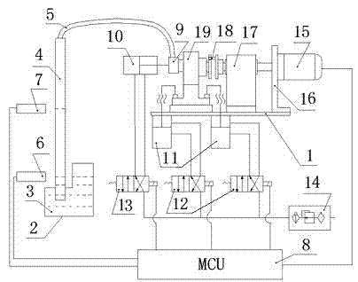
[0016] The following is an oil pump flow dry test method and test device embodiment of the present invention; the test product 19 is a belt drive sprocket oil pump.
[0017] Such as figure 1 As shown: the device of the present invention includes a workbench 1, a fuel tank 2, a hydraulic oil test medium 3, a plexiglass transparent tube 4, a hose 5, a first liquid level sensor 6, a second liquid level sensor 7, an MCU micro control unit 8, Sealing joint 9, oil inlet sealing cylinder 10, clamping rotary cylinder 11, first solenoid valve 12, second solenoid valve 13, pneumatic triple piece 14, servo motor 15, motor bracket 16, bearing seat 17, shift fork 18; The oil tank 2 is installed under the workbench 1, and the oil tank 2 contains the hydraulic oil test medium 3; the lower end of the transparent tube 4 is inserted into the hydraulic oil test medium 3 in the oil tank 2; the installation height of the first liquid level sensor 6 is the same as that of the hydraulic oil test med...
PUM
 Abstract
Description
Claims
Application Information