System for cleaning with rubber balls

A cleaning system and rubber ball technology, applied in the field of rubber ball cleaning system, can solve the problems of low efficiency, complicated operation, high failure rate of water pump and shortened life span, etc. Effect

Active Publication Date: 2012-11-21
TSINGHUA UNIV
View PDF7 Cites 8 Cited by
  • Summary
  • Abstract
  • Description
  • Claims
  • Application Information

AI Technical Summary

Problems solved by technology

[0003] At present, the rubber ball cleaning is mainly based on the rubber ball cleaning technology of the rubber ball pump. Although the rubber ball pump used is designed with a wide flow channel, there is a common problem of severe rubber ball damage and short service life. For air-conditioning chillers and heat pump systems The rubber ball pump with small flow rate still has serious problems such as rubber ball clogging
Although it has also been proposed: the rubber ball cleaning technology based on the jet pump has the problems of low efficiency and low pressure head of the jet pump, and the application area is relatively small; and the double-pump double-circuit rubber ball cleaning technology, that is, the ball-throwing circuit and the ball-receiving circuit Each is equipped with a delivery pump, but at present it mainly adopts the structure of the ball loading room with the top opening and the bottom discharge ball. The rubber balls are blocked at the outlet of the ball collection chamber, especially due to the interval between ball cleaning and ball collection, the rubber balls in the ball collection net cannot be collected in the ball collection chamber in time, causing the rubber balls to block the ball collection net, and the water resistance is relatively large And other issues

Method used


Image

  • System for cleaning with rubber balls
  • System for cleaning with rubber balls
  • System for cleaning with rubber balls

Examples


no. 1 example

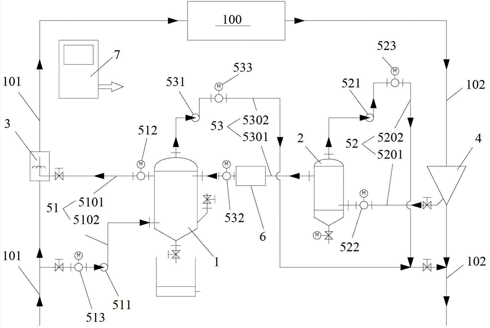
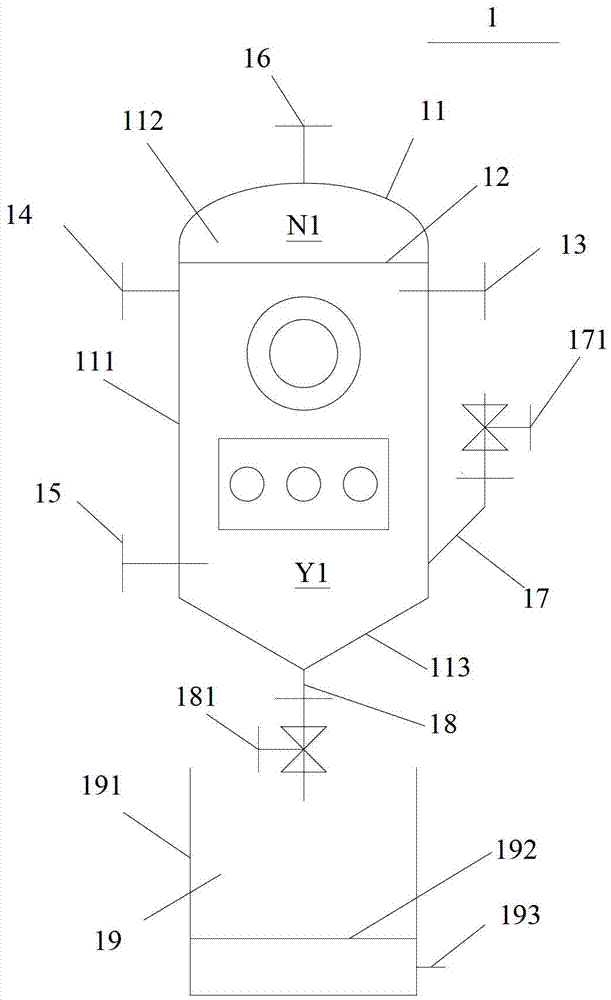
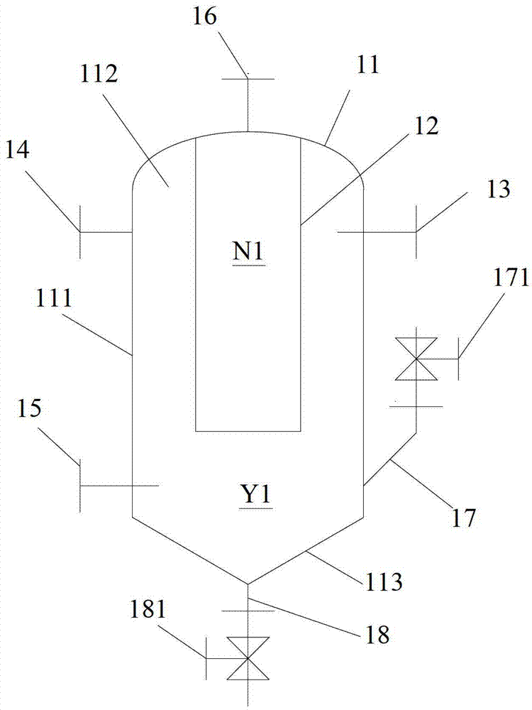
[0056] figure 1 is a schematic diagram of the rubber ball cleaning system provided by the first embodiment of the present invention, figure 2 and image 3 yes figure 1 A schematic structural view of the first ball storage device 1 in the shown rubber ball cleaning system, Figure 4 yes figure 1 The structural representation of the second ball storage device 2 in the shown rubber ball cleaning system, Figure 5 yes figure 1 The connection block diagram of the rubber ball cleaning function piping system in the rubber ball cleaning system shown.

[0057] Such as Figure 1 to Figure 5 As shown, in the first embodiment of the present invention, the rubber ball cleaning system includes rubber ball cleaning functional equipment and rubber ball cleaning functional piping system, and the rubber ball cleaning functional equipment includes a first ball storage device 1, a second ball storage device 2. The ball throwing device 3 and the rubber ball collection device 4, etc., the r...

no. 1 example

[0157] Figure 6 and Figure 7 A modification of the gum ball cleaning system in the first embodiment is shown. Figure 6 The rubber ball cleaning system in figure 1 The rubber ball cleaning systems in the two are basically the same, and the following will only describe the differences between the two, and will not repeat them for the same parts.

[0158] Such as Figure 6 and Figure 7 As shown, a second pitching pipeline 5102 is connected between the water inlet connecting pipe 15 and the input pipeline 101, and the second pitching pipeline 5102 is provided with a second pitching control valve 513 and a pitching water pump 511. Preferably, the pitching water pump 511 is located at The downstream side of the second pitch control valve 513 . A second ball collection pipeline 5202 is connected between the drain connecting pipe 16 and the output pipeline 102. The second ball collection pipeline 5202 is provided with a ball collection water pump 521 and a second ball collect...

no. 2 example

[0166] Figure 8 It is a schematic diagram of the rubber ball cleaning system provided by the second embodiment of the present invention.

[0167] Such as Figure 8 As shown, the second embodiment of the present invention provides a rubber ball cleaning system, the rubber ball cleaning system includes a rubber ball cleaning functional device and a rubber ball cleaning functional pipeline system, the rubber ball cleaning functional device includes a first ball storage device 1. The second ball storage device 2, the ball throwing device 3 and the rubber ball collecting device 4, etc., the rubber ball cleaning function pipeline system 5 includes a ball throwing pipeline 51, a ball collection pipeline 52 and a ball switching pipeline 53, etc., and the ball throwing pipe Road 51 and switching ball pipeline 53 share a pitching and switching ball common pipeline. The rubber ball cleaning function pipeline system connects the input / output pipeline of the equipment to be cleaned with...


PUM


Abstract

The invention discloses a system for cleaning with rubber balls, which comprises a first ball storage device, a ball charging device, a second ball storage device and a rubber ball collecting device, wherein the first ball storage device is provided with a first space with balls, a first space without balls, a ball inlet connecting pipe, a ball outlet connecting pipe, a water inlet connecting pipe and a water outlet connecting pipe, the ball inlet connecting pipe, the ball outlet connecting pipe and the water inlet connecting pipe are connected with the first space with balls, and the water outlet connecting pipe is connected with the first space without balls; the ball charging device is arranged on an input pipeline and used for charging rubber balls in the first space with balls into a device to be cleaned; the second ball storage device is provided with a second space without balls, a second space with balls, a feed connecting pipe, a discharge connecting pipe and a water discharge connecting pipe, the feed connecting pipe and the discharge connecting pipe are connected with the second space with balls, and the water discharge connecting pipe is connected with the second space without balls, and the rubber balls inside the second space with balls can be allowed to enter the first space with balls; and the rubber ball collecting device is used for collecting the rubber balls discharged by the device to be cleaned and allowing the rubber balls to enter the second space with balls. In the system for cleaning, disclosed by the invention, the service lives of the rubber balls and a water pump are long, the water resistance of the system is small, and the energy-saving effect is obvious.

Description

technical field [0001] The invention relates to the technical field of rubber ball cleaning, in particular to a rubber ball cleaning system. Background technique [0002] Water-cooled power plant condensers generally have the problem of fouling and fouling during operation, which has a very important impact on the thermal efficiency of the unit and the life of the equipment. For this reason, rubber ball cleaning is generally used for online descaling and antiscaling of condensers in water-cooled power plants, so as to achieve energy saving and consumption reduction and prolong the effective service life of equipment. Rubber ball cleaning is also suitable for air-conditioning chillers and heat pump heat exchange systems. [0003] At present, the rubber ball cleaning is mainly based on the rubber ball cleaning technology of the rubber ball pump. Although the rubber ball pump used is designed with a wide flow channel, there is a common problem of severe rubber ball damage and ...

Claims


Application Information

Patent Timeline
Patent Type & Authority Applications(China)
IPC IPC(8): F28G1/12F28G15/00
Inventor 孟继安
Owner TSINGHUA UNIV
Why Eureka
Try Eureka