Method for acquiring geometric correction parameter of PET (positron emission tomography) system

A geometric correction and parameter technology, applied in the field of obtaining PET system geometric correction parameters, can solve the problems of inflexibility, complicated operation process, economic cost, time and manpower consumption, etc., to ensure accuracy, speed up design, and simple process Effect

Active Publication Date: 2012-11-21
SHANGHAI RES CENT OF BIOMEDICAL ENG
View PDF2 Cites 23 Cited by
  • Summary
  • Abstract
  • Description
  • Claims
  • Application Information

AI Technical Summary

Problems solved by technology

[0006] Because the acquisition method of the above-mentioned known geometric correction parameters needs to establish an actual measurement environment (such as needing a set of actual PET system that can work normally, need to customize a special measured physical model, etc.), the operation process is complicated when measuring data, economic

Method used


Image

  • Method for acquiring geometric correction parameter of PET (positron emission tomography) system
  • Method for acquiring geometric correction parameter of PET (positron emission tomography) system
  • Method for acquiring geometric correction parameter of PET (positron emission tomography) system

Examples


Example Embodiment

[0028] Example one

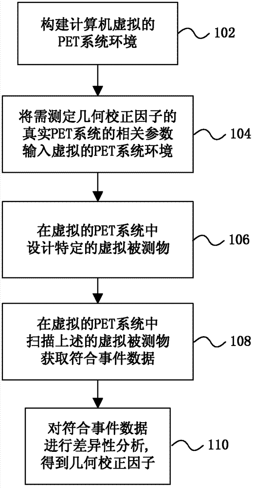
[0029] This embodiment provides a method for obtaining the geometric correction parameters of the PET system. The method is based on computer simulation. A virtual PET system identical to the actual PET system is constructed through software. In the virtual PET system, a specially designed virtual test object is performed. After scanning, the relevant event data is obtained, and then the difference is compared and analyzed to obtain the geometric correction parameters.

[0030] The process of the method for obtaining the geometric correction parameters of the PET system is as follows figure 1 As shown, including the following steps:

[0031] Step 102: Construct a virtual PET system environment by writing a set of computer software based on Monte Carlo simulation technology. The principle of Monte Carlo simulation technology is well known, and its accuracy and reliability have also been confirmed by many scientific research documents. The computer software writt...

Example Embodiment

[0041] Example two

[0042] The difference between this embodiment and the first embodiment is that in step 102, a virtual PET system environment, such as GATE (Geant4 Application for Tomographic Emission), is constructed through open source computer software.

Example Embodiment

[0043] Example three

[0044] This embodiment verifies the effect of the method for obtaining the geometric correction parameters of the PET system described in the first embodiment, and the verification process is as follows:
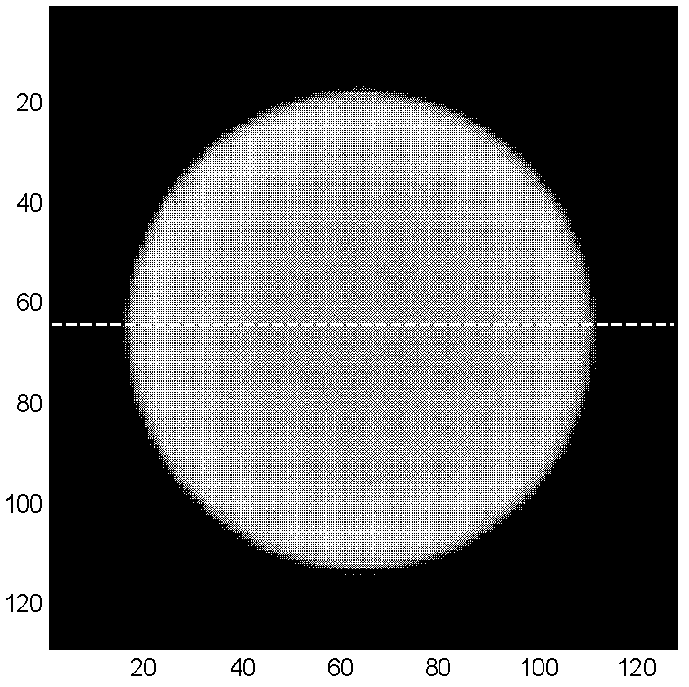
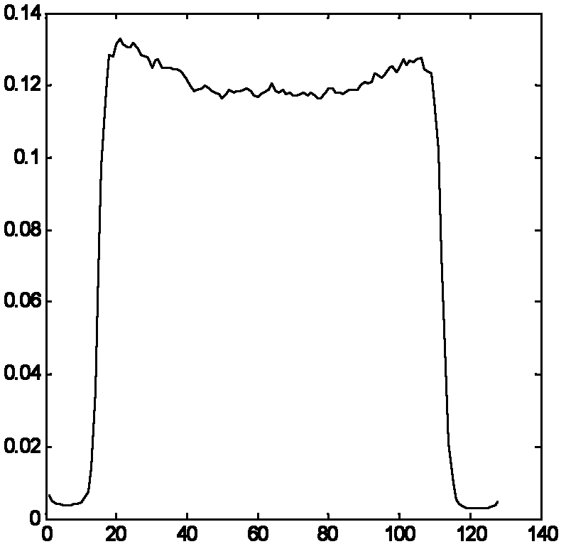
[0045] In an actual PET system, the uniform cylinder is scanned first to obtain the measured coincidence event data; then the image is reconstructed based on the measured coincidence event data, and the PET image of the measured uniform cylinder can be obtained. The gray value in the figure represents the intensity of radioactivity. The larger the area gray value (the image is white and bright), the stronger the radioactive intensity of the area; the smaller the area gray value (the dark image), the weaker the radioactive intensity of the area. Theoretically, the gray value of the cross-sectional image of a uniform cylinder PET image is almost equal in a circular area. In other words, the brightness of a circular area in the cross-sectional view is unifor...


PUM


Abstract

The invention discloses a method for acquiring a geometric correction parameter of a PET (positron emission tomography) system. The method comprises the steps of 1) building a virtual PET system environment by using computer software; 2) inputting the related parameter of a real PET system of which the geometric correction parameter needs to be measured into the virtual PET system environment; 3) designing a specific virtual measured object in the virtual PET system environment; 4) scanning the specific virtual measured object in the virtual PET system environment to acquire coincidence data; and 5) performing difference analysis to the coincidence data to obtain the geometric correction parameter. According to the method, preparation for object PET equipment and a measured object model is eliminated, and the process of acquiring the geometric correction parameter is simple, economical, quick and free from the limit of environment factor, and therefore, the accuracy of the geometric correction parameter is ensured. In addition, the method can be executed before or after development and production of the PET system, so that the design, development and production period of the PET system is accelerated.

Description

technical field [0001] The invention belongs to the technical field of medical imaging equipment, and relates to a method for obtaining geometric correction parameters of a PET system. Background technique [0002] Positron Emission Tomography (PET) system is a radionuclide tracer imaging system. Usually the detected object contains radionuclide-labeled tracer substances. Radionuclides emit positrons upon decay. The positron annihilates with a neighboring electron, producing a pair of 511KeV gamma (γ) photons flying in opposite directions. When the gamma photon is collected by a pair of PET detection units within a certain time window, an event mark is generated, which is called a coincidence event. The coincidence event records information such as the spatial position of the pair of PET detection units. Therefore, it can be determined that annihilation has occurred at a certain position on the connection line (referred to as coincidence line) between the pair of PET det...

Claims


Application Information

Patent Timeline
IPC IPC(8): G06F17/50A61B6/03
Inventor 张晓俞王新谢舒平
Owner SHANGHAI RES CENT OF BIOMEDICAL ENG
Why Eureka
Try Eureka