Superconductivity flat wave current limiting reactor applicable to high-voltage direct-current transmission

A technology of high-voltage DC transmission and current-limiting reactors, which is applied in transformer/inductor cores, transformers, superconducting magnets/coils, etc., and can solve the problem of high energy consumption of ordinary smoothing reactors and difficulty in breaking and short-circuiting of DC circuit breakers Current and other issues, to achieve the effect of no fire hazard, light weight, low energy consumption

Inactive Publication Date: 2012-11-21
INST OF ELECTRICAL ENG CHINESE ACAD OF SCI
View PDF7 Cites 10 Cited by
  • Summary
  • Abstract
  • Description
  • Claims
  • Application Information

AI Technical Summary

Problems solved by technology

[0006] The purpose of the present invention is to overcome the shortcomings of the existing DC circuit breaker in the field of high-voltage direct current transmission that it is difficult to break the short-circuit current and the energy consumption of ordinary smoothing reactors is high, and proposes a superconducting smoothing reactor with both smoothing and current limiting functions. Flow reactor

Method used


Image

  • Superconductivity flat wave current limiting reactor applicable to high-voltage direct-current transmission
  • Superconductivity flat wave current limiting reactor applicable to high-voltage direct-current transmission
  • Superconductivity flat wave current limiting reactor applicable to high-voltage direct-current transmission

Examples


Embodiment 1

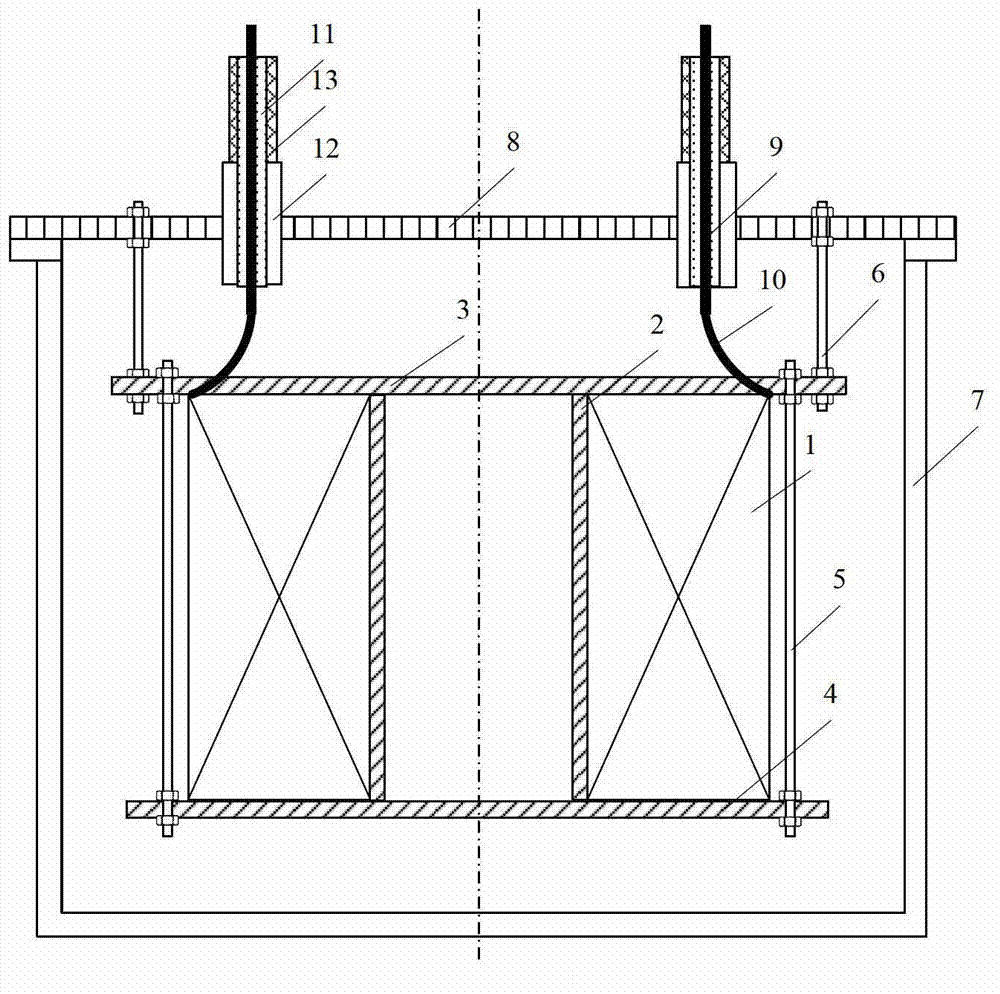
[0030] Embodiment 1 is a superconducting smoothing current-limiting reactor with an air-core structure. Such as figure 2 As shown, the superconducting flat-wave current-limiting reactor consists of a superconducting coil 1, a coil frame 2, a coil upper support plate 3, a coil lower support plate 4, a coil fastening screw 5, a pull rod 6, a low-temperature Dewar cylinder 7, and a low-temperature dewar Tile cover plate 8, current lead wire 9, transition line 10, sleeve insulation layer 11, sleeve low temperature insulation layer 12 and sleeve normal temperature insulation layer 13 are formed. A superconducting coil 1, a coil frame 2, an upper coil support plate 3, a coil lower support plate 4, and a coil fastening screw 5 form a superconducting magnet. The superconducting coil 1 is wound outside the bobbin 2 , the upper coil support plate 3 and the lower coil support plate 4 are respectively located at the upper and lower parts of the superconducting coil 1 , and the supercond...

Embodiment 2

[0033] Embodiment 2 The superconducting smoothing current-limiting reactor applied to high-voltage direct current transmission adopts an iron-core reactor structure with a gap. Such as Figure 6 As shown, the superconducting flat-wave current-limiting reactor consists of a superconducting coil 1, a coil frame 2, a coil upper support plate 3, a coil lower support plate 4, a coil fastening screw 5, a low-temperature Dewar cylinder 7, and a low-temperature Dewar upper cover Plate 8, current lead wire 9, transition line 10, sleeve insulation layer 11, sleeve low temperature insulation layer 12, sleeve normal temperature insulation layer 13, iron core 14, gap 15, coil upper pad 16, coil lower pad 17 and Block 18 under the iron core constitutes. A superconducting coil 1, a coil frame 2, an upper coil support plate 3, a coil lower support plate 4, and a coil fastening screw 5 form a superconducting magnet. The superconducting coil 1 is wound outside the bobbin 2 , the upper coil su...

Embodiment 3

[0035] Embodiment 3 is another iron core reactor structure with a gap used in the superconducting smoothing current-limiting reactor applied to HVDC transmission. Such as Figure 7 As shown, the superconducting flat-wave current-limiting reactor consists of a superconducting coil 1, a coil frame 2, a coil upper support plate 3, a coil lower support plate 4, a coil fastening screw 5, a low-temperature Dewar cylinder 7, and a low-temperature Dewar upper cover Plate 8, current lead wire 9, transition line 10, sleeve insulation layer 11, sleeve low temperature insulation layer 12, sleeve normal temperature insulation layer 13, iron core 14, gap 15 and iron core lower pad 18 constitute. A superconducting magnet is composed of a superconducting coil 1 , a coil frame 2 , an upper coil support plate 3 , a coil lower support plate 4 , and a coil fastening screw 5 .

[0036] Same as Embodiment 1, the superconducting coil 1 is wound outside the coil frame 2, the coil upper support plate...


PUM

PropertyMeasurementUnit
current densityaaaaaaaaaa

Abstract

Provided is a superconductivity flat wave current limiting reactor applicable to high-voltage direct-current transmission. A superconducting magnet composed of a superconducting coil (1), a coil frame (2), a coil upper supporting plate (3), a coil lower supporting plate (4) and a coil fastening screw (5) is arranged inside a low-temperature dewar device composed of a low-temperature dewar drum (7) and a low-temperature dewar upper cover plate (8). The superconducting magnet is cooled through direct evaporating of liquid nitrogen or cooled through the liquid nitrogen added into a refrigerator. The superconducting magnet is installed with the low-temperature dewar upper cover plate (8) through a pull rod (6). The superconducting magnet and a transition line (10) are connected with a direct current power grid through a current lead wire (9). A sleeve heat preservation layer (11), a sleeve low-temperature insulation layer (12) and a sleeve normal-temperature insulation layer (13) are arranged outside the current lead wire (9), good insulation is guaranteed, and heat leakage is reduced. The superconductivity flat wave current limiting reactor has no loss and only a flat wave effect is obtained when the direct current power grid works normally. When the direct current power grid is short-circuited, resistance of the reactor is increased fast, and short-circuit current is restrained to certain level.

Description

technical field [0001] The invention relates to a reactor used in the field of high voltage direct current transmission. Background technique [0002] Compared with AC transmission, high-voltage direct current transmission has irreplaceable advantages: low line cost, simple power adjustment, no need for stable and synchronous operation of both ends of the system, and small corona interference. DC transmission has been widely used in long-distance high-power transmission, cable transmission and other aspects. In recent years, the emergence of flexible DC transmission has extended DC transmission to short-distance and small-capacity transmission occasions. Although the development of DC transmission technology has been relatively mature, compared with the flexible and diverse connection methods of AC transmission systems, most of the DC systems in operation in the world still use two-terminal systems. The main reason is the lack of practical high-voltage DC circuit breakers. ...

Claims


Application Information

Patent Timeline
Patent Type & Authority Applications(China)
IPC IPC(8): H01F36/00H01F6/06H01F6/04H01F27/24
CPCY02E40/66Y02E40/60
Inventor 邱清泉戴少涛肖立业林良真张京业张志丰宋乃浩
Owner INST OF ELECTRICAL ENG CHINESE ACAD OF SCI
Why Eureka
Try Eureka