

Flow battery
An electrochemical and battery technology, applied in electrochemical generators, fuel cells, battery electrodes, etc., can solve problems such as high price, low battery performance, and easy corrosion of conductive parts
- Summary
- Abstract
- Description
- Claims
- Application Information
AI Technical Summary
Problems solved by technology
Method used
Image

Examples
example 2
[0090] Example 2: Complexed iron / bromine flow battery.
[0091] negative electrode:
[0092] positive electrode:
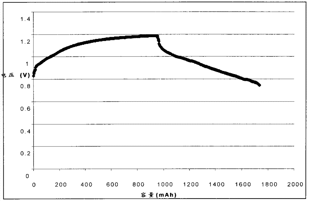
[0093] At the beginning of charging, 50 ml of negative electrolyte (1M K 3 [Fe(CN) 6 ] And 1M NaOH solution) were injected into the negative electrode structure. 50 ml of catholyte solution (1M NaBr and 1M NaOH solution) was injected into the positive electrode structure. Constant current charging 20mA / cm 2 About 1 hour. Figure 4 Given that the battery is at 20mA / cm 2 Charging and discharging curve characteristics. by Figure 4 It can be seen that the charge and discharge voltage of the battery is relatively low, about 0.6 to 0.7V.
example 3
[0094] Example 3: Complexed copper / bromine flow battery.
[0095] negative electrode:
[0096] positive electrode:
[0097] m is usually 4, n is usually 2, water molecules and hydroxide radicals can also participate in coordination. At the beginning of charging, 75 ml of anolyte solution, 1M complex ion [Cu(NH 3 ) 4 (H 2 O)x] 2+ The solution is injected into the negative structure. 75 milliliters of catholyte and 1M NaBr solution are injected into the positive electrode structure. Constant current charging 20mA / cm 2 About an hour. Figure 4 Given that the battery is at 20mA / cm 2 Charging and discharging curve characteristics. by Figure 5 It can be seen that the charge and discharge voltage of the battery is relatively reasonable, which is below the electrolysis voltage of water, but very close. The steps of charge and discharge voltage are relatively gentle, showing good dynamic characteristics.
[0098] The invention provides a flow battery for storing electric energy by elec...
PUM
| Property | Measurement | Unit |
|---|---|---|
| Conductivity | aaaaa | aaaaa |
| Concentration | aaaaa | aaaaa |
Abstract
Description
Claims
Application Information