Automatic rapid protection control method of novel feeder

A feeder automation and protection control technology, applied to emergency protection circuit devices, electrical components, circuit devices, etc., can solve problems such as time limit coordination, difficult setting, and inability to guarantee selectivity, so as to achieve the effect of isolation

Active Publication Date: 2012-11-21
SHANDONG UNIV
View PDF1 Cites 46 Cited by
  • Summary
  • Abstract
  • Description
  • Claims
  • Application Information

AI Technical Summary

Problems solved by technology

Generally, three-stage overcurrent protection is set in the protection device, and the upstream and downstream protections are completed through the cooperation of the time limit. However, this method is difficult to set when the distribution network is reconfigured, and the selectivity cannot be guaranteed.
[0004] In order to improve the speed of action, the field has successively proposed: 1. No channel protection for distribution lines. The core idea is to trip the circuit breaker on the opposite side according to the change in the electrical quantity of the line after the circuit breaker on one side trips, but this solution still needs Time limit cooperation; 2. The distributed self-healing feeder protection scheme uses the fault power direction to determine the fault section, which can realize rapid fault removal, but the detection of the fault power direction requires voltage, which limits the practicability of the scheme; 3 .A full-line fast-acting distribution line protection scheme. The protection needs to integrate the information of each FTU to achieve accurate isolation of the fault section, but this method is similar to the centralized protection method of the current distribution automation system.

Method used


Image

  • Automatic rapid protection control method of novel feeder
  • Automatic rapid protection control method of novel feeder
  • Automatic rapid protection control method of novel feeder

Examples


Embodiment Construction

[0028] specific implementation plan

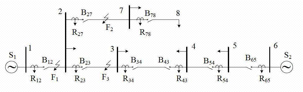
[0029] figure 1 shows a common distribution network structure with branch lines, S 1 , S 2 It is a 10kV power supply; the node number of the line is 1~8, and the line between nodes 2, 7, and 8 is a branch line; B ij is the line switch, where B 43 It is a contact switch; install STU at each switch, and configure the protection element in each STU, figure 1 Middle R ij It is the overcurrent element configured in the STU. Adjacent STUs are connected through optical fiber Ethernet to form a ring network and finally connected to the feeder automation master station.

[0030] In order to facilitate the analysis of the characteristics of the fault current, with the tie switch as the boundary, the positive direction of the current is defined as the load from the power sources on both sides to the loads on each side. During normal operation, switch B 43 disconnect. If F 1 If a phase-to-phase fault occurs at each point, whether each protec...


PUM


Abstract

The invention particularly discloses an automatic rapid protection control method of a novel feeder. The automatic rapid protection control method comprises the following steps of: 1, mounting an STU (smart terminal unit) on each circuit switch and each interconnection switch in a network distribution structure, configuring a protective element into each STU, connecting the adjacent STUs, forming an annular network, and finally, connecting the annular network to an automatic main station of the feeder; 2, configuring each element in network distribution; 3, rapidly identifying a fault by the STUs according to local and adjacent current information and switch position information; 4, transmitting the fault identifying result to the adjacent STUs and the automatic main station of the feeder through a communication network by the STUs, and 5, carrying out isolation and power supply restoration on the fault. The automatic rapid protection control method has the beneficial effects that: an FTU (feeder terminal unit) in an original feeder is upgraded into the STU with intelligent judgment ability; and the fault section can be rapidly located by the local and adjacent current information and switch position information, so that isolation of a fault area and the power supply restoration of a non-fault area are achieved.

Description

technical field [0001] The invention relates to a novel feeder automatic fast protection control method. Background technique [0002] The distribution network is an important part of the smart grid. Its construction goal is to make it have a complete fault self-healing function, which can minimize the impact of distribution network faults on users, and support the access of a large number of distributed power sources. But at present, the grid structure of the distribution network is weak, and the secondary protection and control technology is not perfect, which makes the power outage accidents of the distribution network occur from time to time. Statistics show that more than 80% of the faults in the power grid occur in the power distribution system. It can be seen that the protection control of distribution network and its fault self-healing technology are directly related to the operation efficiency of the entire distribution system and the power quality of end users. ...

Claims


Application Information

Patent Timeline
Patent Type & Authority Applications(China)
IPC IPC(8): H02H7/26H02J13/00
CPCY04S10/20Y02E60/725Y02E60/00
Inventor 邹贵彬高厚磊王玥婷仝冰冰石明垒
Owner SHANDONG UNIV
Why Eureka
Try Eureka