
Servo drive system and speed ring parameter setting system thereof

A servo drive and parameter tuning technology, applied in the control system, vector control system, motor generator control, etc., can solve the problems of complicated and complicated tuning process and limited tuning accuracy, and achieve the effect of simple tuning process and high tuning accuracy.

Active Publication Date: 2012-11-21
KEDE NUMERICAL CONTROL CO LTD
View PDF3 Cites 8 Cited by
  • Summary
  • Abstract
  • Description
  • Claims
  • Application Information

AI Technical Summary

Problems solved by technology

[0005] The purpose of the embodiment of the present invention is to provide a servo drive system to solve the problem that in the servo drive system provided by the prior art, the control parameters of the speed loop need to be manually adjusted by the operator on site to complete the setting of the speed change parameter, and the setting process is cumbersome and complicated. And the problem of limited tuning accuracy

Method used


Image

  • Servo drive system and speed ring parameter setting system thereof
  • Servo drive system and speed ring parameter setting system thereof
  • Servo drive system and speed ring parameter setting system thereof

Examples


Embodiment Construction

[0055] In order to make the object, technical solution and advantages of the present invention clearer, the present invention will be further described in detail below in conjunction with the accompanying drawings and embodiments. It should be understood that the specific embodiments described here are only used to explain the present invention, not to limit the present invention.

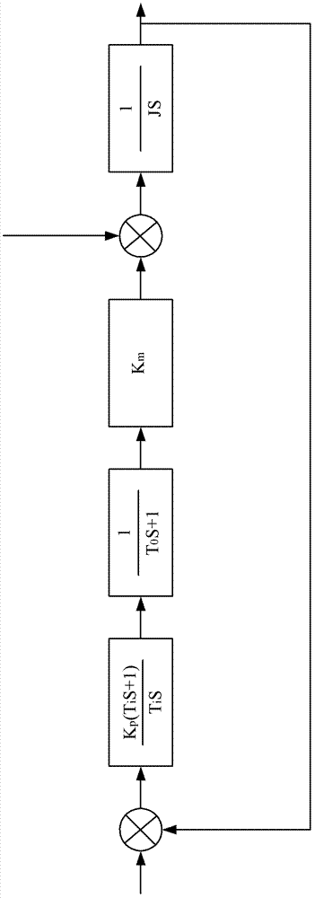
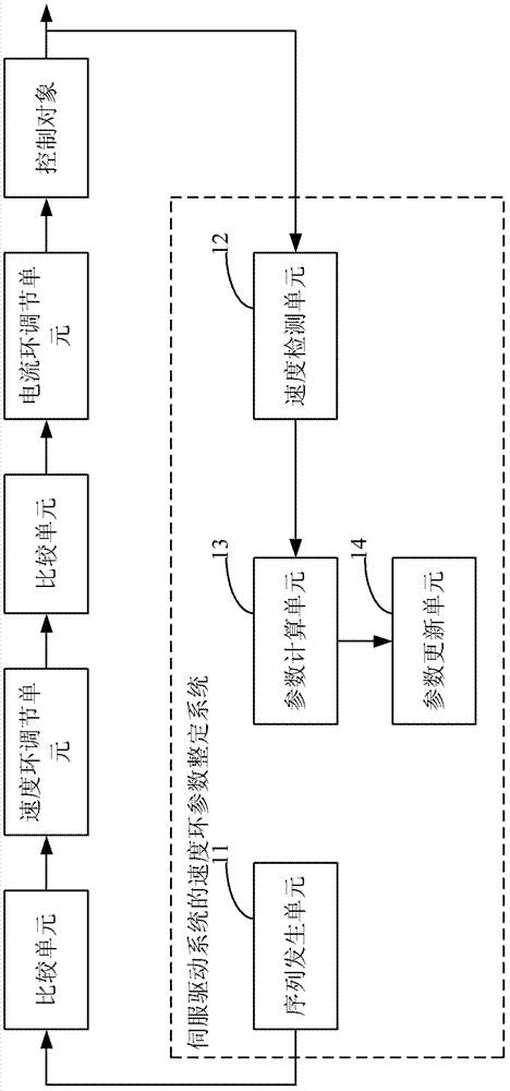
[0056] figure 2 show figure 1 Structure. in, is the transfer function of the speed loop regulator, the proportional gain K p and integration time T i Together as the speed loop parameters; is the transfer function of the equivalent control link of the current loop, T 0 is the equivalent inertial time constant of the current loop; K m is the electromagnetic torque coefficient; T 1 is the load disturbance; J is the moment of inertia of the mechanical mechanism. In order to realize the speed loop parameter K in the servo drive system p and T i setting, such as image 3 The principle of...


PUM


Abstract

The invention discloses a servo drive system. The servo drive system comprises a speed ring parameter setting system of the servo drive system, wherein the speed ring parameter setting system further comprises a sequence generating unit, a speed detecting unit, and a parameter calculating unit, wherein the sequence generating unit is used for generating and outputting a sequence signal of fixed quantity as a speed ring; the speed detecting unit is used for acquiring a speed feedback value for controlling object feedback; the parameter calculating unit is used for calculating proportional gain and integral time as the speed ring parameter according to the sequence signal and the speed feedback value. The servo drive system provided in the invention injects a sequence signal to the speed ring of the current servo drive system by the speed ring parameter setting system of the servo drive system, uses the sequence signal and the speed value of the control object when the sequence signal is used as the speed fixed variable to calculate the self-setting for the speed ring parameters Kp and Ti of the servo drive system; the setting process is simple, time-saving and force-saving, free of the experience of debugging staffs and high in setting precision.

Description

technical field [0001] The invention belongs to the technical field of automatic control, in particular to a servo drive system and a speed loop parameter setting system thereof. Background technique [0002] A servo drive system refers to a feedback control system that can accurately follow or reproduce a certain process. With the maturity of AC motor control theory and the development of AC servo motor in the technical fields of microelectronics, computer and power electronics, vector control and some complex control algorithms can be realized in engineering applications, thus making AC servo drive system in CNC Machine tools, robots and other fields have been widely used. [0003] The current servo drive system adopts a control structure combining vector control and PID control, which is usually a three-loop control of current loop, speed loop and position loop. Among them, the current loop control can suppress the interference of power fluctuations and improve the resp...

Claims


Application Information

Patent Timeline
Patent Type & Authority Applications(China)
IPC IPC(8): H02P21/14
Inventor 李作庆李文庆王庆朋吴孔圣陈虎韩贵春李俊王声文王大伟江世琳
Owner KEDE NUMERICAL CONTROL CO LTD
Learn More